所需物品:
Formlabs:
- 主板
- 2.5mm 六角扳手(包含在 Form 4 工具箱中)
第三方:
- 2mm 六角扳手
- 丁腈手套
- 防静电接地带

主板是 Form 4 上的主要电子模块,用于控制各种子系统。主板连接到打印机,位于右侧面板后方。若主板出现故障,打印机将无法正常打印。
请根据本指南更换 主板。
所需物品:
Formlabs:
第三方:
预计所需时间: 2 小时
注意:
在本更换指南中,需要接触 Form 4 内的精密电子元件。静电放电会损坏这些电子元件。进行此操作时,Formlabs 建议使用防静电接地带。
准备工作区
概览: 准备好打印机和无尘的工作区,以便更换主板。
第 1 步:拆卸构建平台
首先,拆卸构建平台,防止树脂滴落到 Light Processing Unit (LPU) 上。
第 2 步:拆卸树脂盒
拆卸树脂盒并关闭通气帽,以防止树脂从咬阀上滴入打印机。
第 3 步:拆卸并存放树脂槽和混合器
解锁混合器和树脂槽。取出树脂槽并盖上盖子。将树脂槽放置在干净、平整的表面上。
注意:
请戴上手套,握住树脂槽两端的把手,以免污染或损坏树脂槽的底面。
第 4 步:准备工作区
清理打印机周围的工作区。确保工作区通风良好且没有灰尘。 为存放以下物品预留额外空间: 外部面板、LPU、树脂槽锁销、触摸屏和打印机 以防意外启动打印机
第 5 步:清洁打印机
警告:
树脂可能引起皮肤刺激或皮肤过敏反应。处理液态树脂或树脂涂层表面时,请戴上手套。请使用大量肥皂和水冲洗皮肤。
打开打印机机罩,用防磨损抹布清理 LPU 上及其周围积聚的树脂。如有必要,可使用异丙醇沾湿抹布,彻底清除树脂。
危险:
IPA 属于易燃物,存在火灾隐患。请始终盖好容器盖子,防止儿童接触。
第 6 步:断开打印机电源
请断开电源线后再继续进行维护。在打印机通电时,请勿对打印机执行维护程序。断开打印机电源后,等待五分钟,然后再继续执行维护程序。
危险:
在打印机通电时进行维护会增加触电危险。在打印机通电时,切勿拆除打印机后面板。后面板尚未安装时,切勿重新接通打印机电源。
Step 7: Check the motherboard fasteners
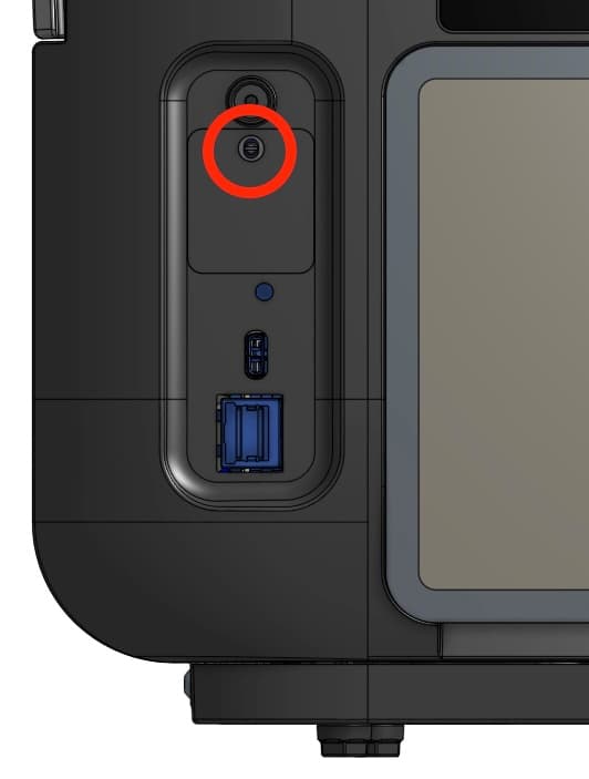
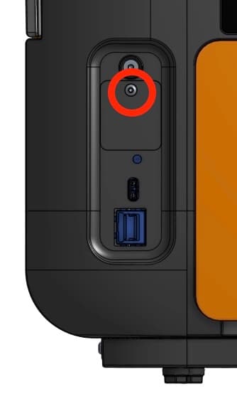
How the motherboard is secured to a Form 4 generation printer depends on when the printer was manufactured. Printers manufactured on or after November 15, 2024 have four screws, accessible by removing the right panel from the printer. Printers manufactured before November 15, 2024 have six screws, two of which require removing additional panels from the printer.
To determine which you have, peel back the serial name sticker on the back-left of the printer. If you see a hex screw, you have an older unit. Continue following the instructions in this guide. If you see a slotted stud, you have a newer unit. Follow the instructions in the guide Replacing the Form 4 motherboard (post 2024-11-15).
拆卸外部面板
概览: 取下 外部面板和后部筛网,以便操作主板。
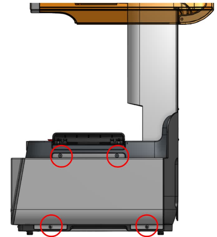
打开打印机机罩。使用 2.5mm 六角扳手 将左侧外部面板固定在打印机上的四颗螺丝。将左侧外部面板和螺丝放在一旁。
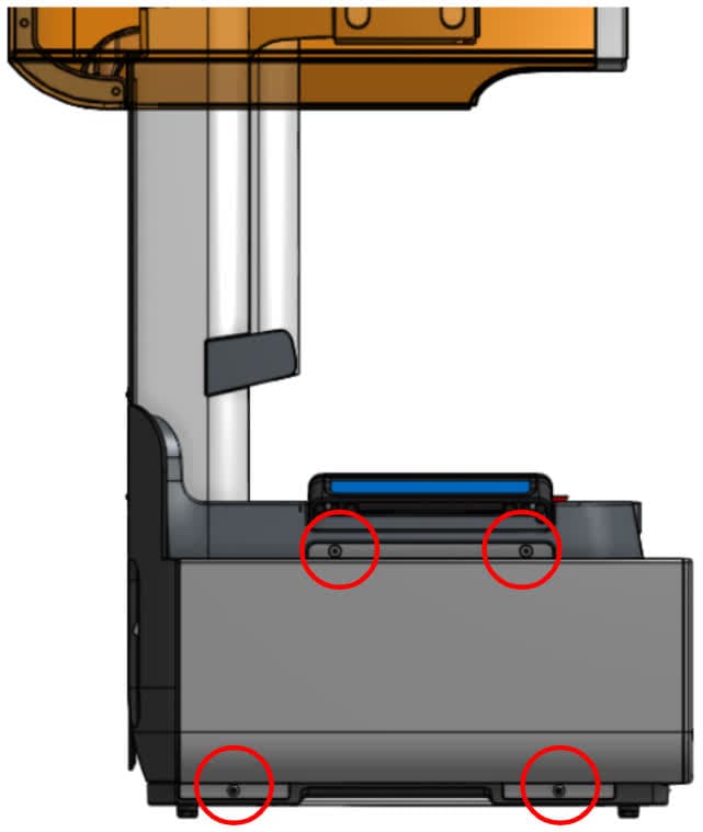
使用 2.5mm 六角扳手 拧下将右侧外部面板固定在打印机上的 4 颗螺丝。将右侧外部面板和螺丝放在一旁。
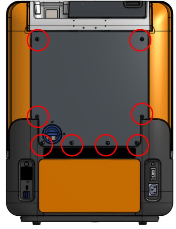
使用 2.5mm 六角扳手,拧下将后面板固定在打印机上的 8 颗螺丝。将后面板向下滑离打印机背面,取下后面板。将后面板和螺丝放在一旁。
第 4 步:拆卸后部筛网
拆卸磁性后部筛网并将其放在一旁。
拆卸 LPU
概览: 拧松外壳螺丝,取出 LPU。
注意:
此步骤包括拆卸 LPU,从而露出 Form 4 光学系统。从打印机上取下 LPU 时,确保没有灰尘或碎屑掉入光学共振腔。
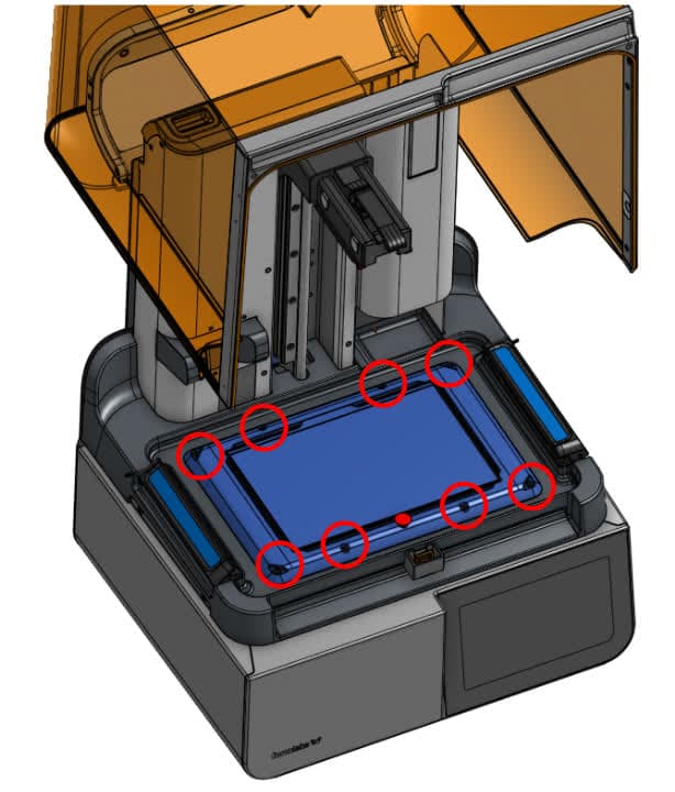
打开打印机机罩。使用 2.5mm 六角扳手拧松 LPU 外壳上的八颗六角螺丝。
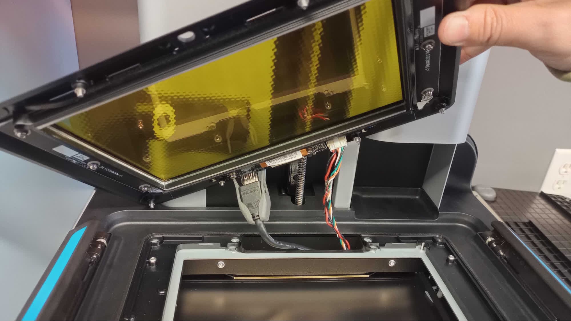
小心提起 LPU 并将其倾斜,使底部朝向您。找到 LPU 的 HDMI 电缆。挤压塑料固定夹,从 LPU 拔下 HDMI 电缆。
第 3 步:断开树脂槽加热器电缆
松开树脂槽加热器电缆,方法是挤压连接器上的插片,然后直接拉离 LPU。请勿拉扯电缆本身。
第 4 步:拆卸 LPU
从打印机中取出 LPU 并将其放在一旁。
拆卸树脂槽锁销
概览: 找到固定插片,取下销钉和弹簧,拆卸树脂槽锁销。
树脂槽锁销通过两个金属销钉连接到打印机上,金属销钉由固定插片固定。提起树脂槽锁销,找到每个锁销后方的黑色固定插片。
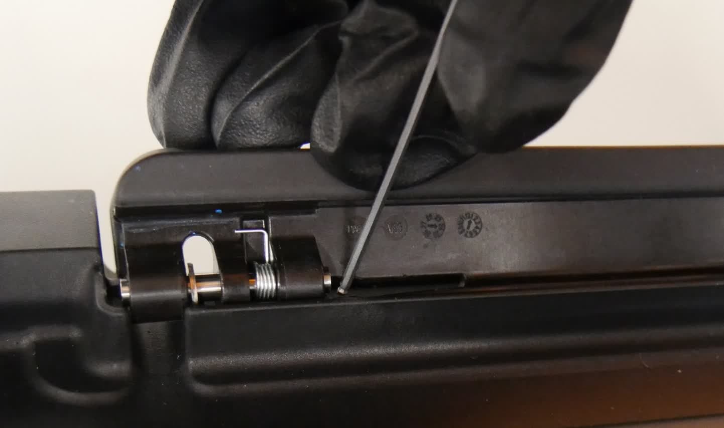
第 2 步:取下销钉和弹簧
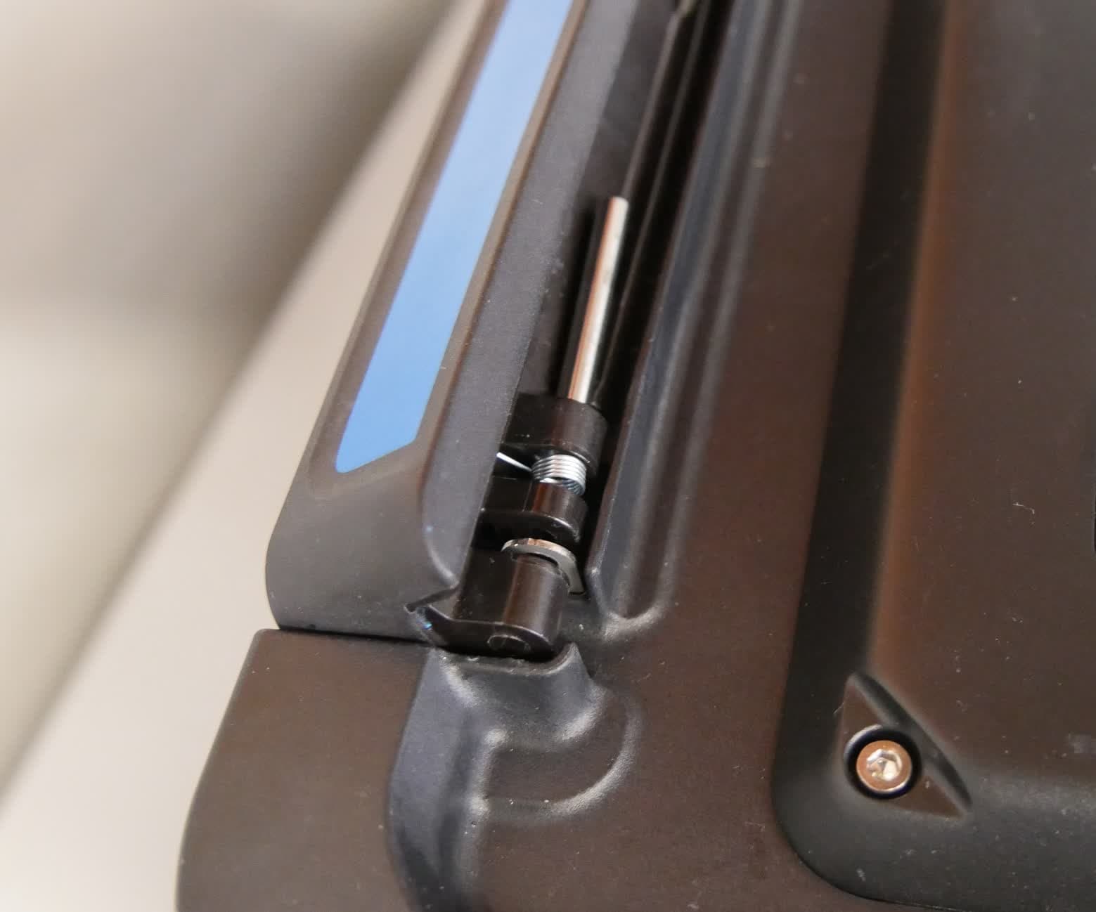
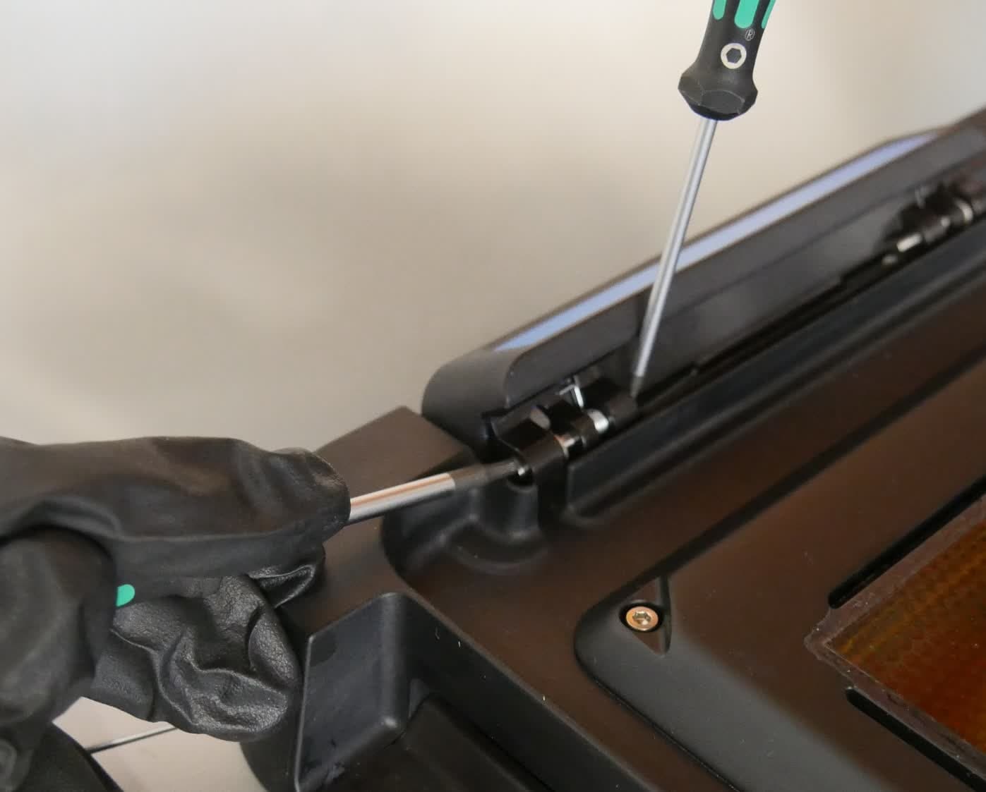
While pressing down on the retaining tab with the 2.5 mm hex driver, use the 2 mm ball-end hex driver to push the pin through the bracket. You may need to use a moderate amount of force to fully push the pin out of its bracket. Once the pin is removed, the spring separates from the bracket. Set the spring and pin aside.
Step 3: Remove the second pin
Repeat steps 1–2 to remove the second pin from the resin tank latch. Note that there is only one spring per latch. The pin with the spring is located closer to the front of the printer.
Step 4: Remove the second resin tank latch
Repeat steps 1–3 to remove the second resin tank latch. Set the resin tank latches aside.
拆卸触摸屏组件
概览: 从打印机上取下触摸屏组件。
第 1 步:将混合器底座居中
打开打印机机罩,将混合器底座滑到 LPU 中心位置。
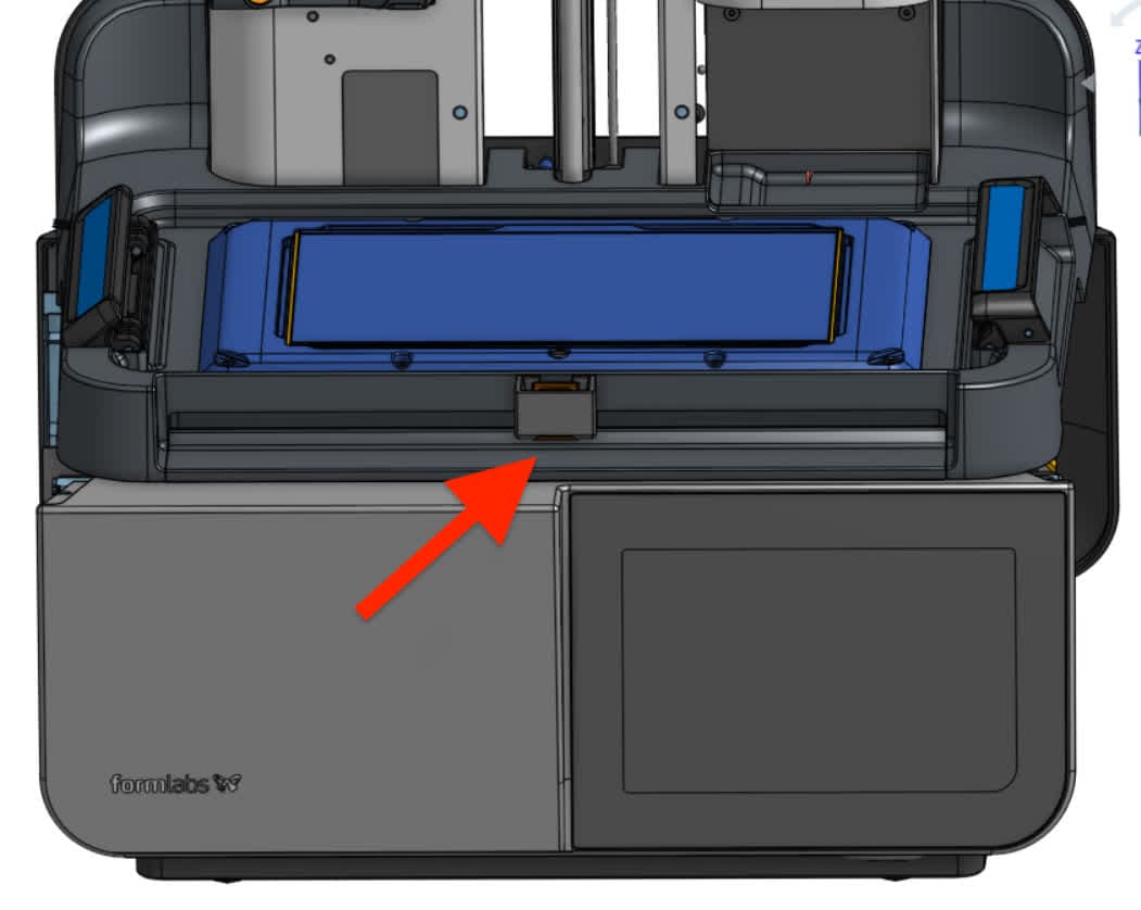
使用 2.5mm 六角扳手,拧下将左侧触摸屏组件固定到打印机上的 3 颗螺丝。将螺丝放在一旁。
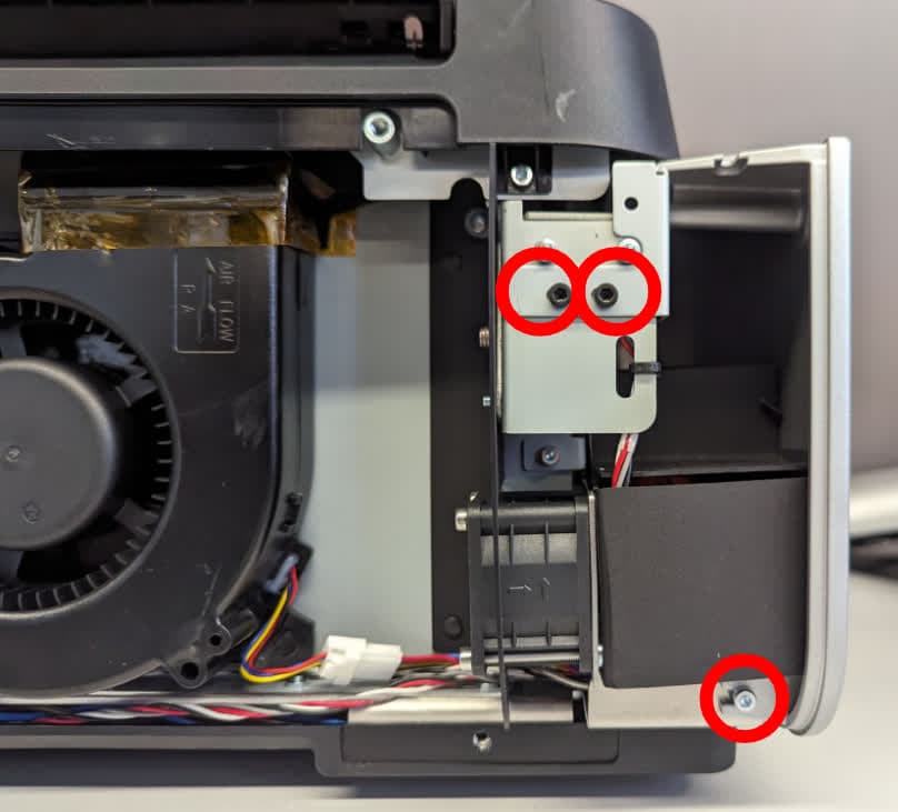
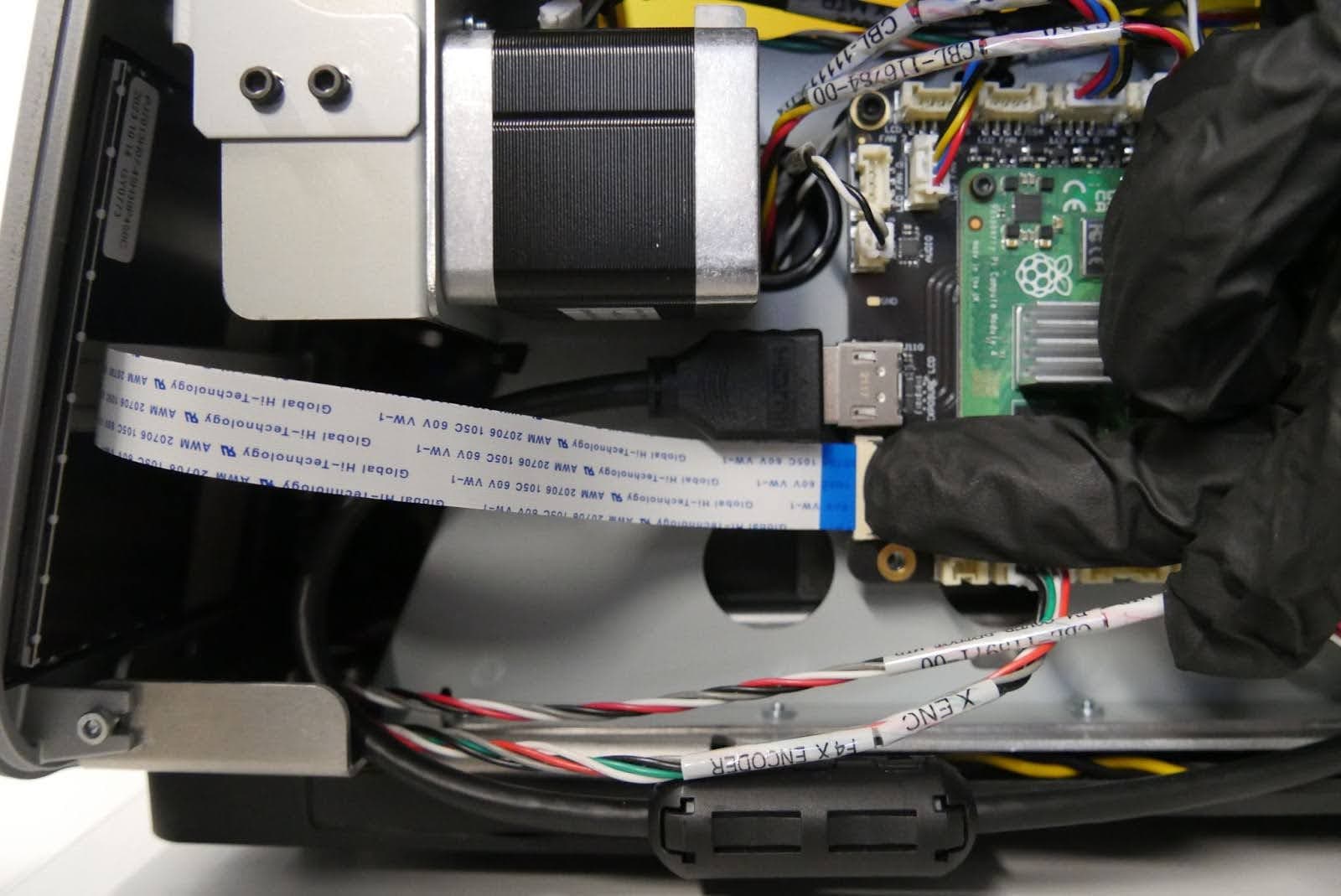
触摸屏带状电缆由锁销固定。将连接器上的黑色塑料插片旋转到远离打印机的位置,从主板上松开触摸屏带状电缆。请勿拉扯触摸屏带状电缆。一旦正确松开黑色插片,以最小的力即可将电缆从连接器中滑出。
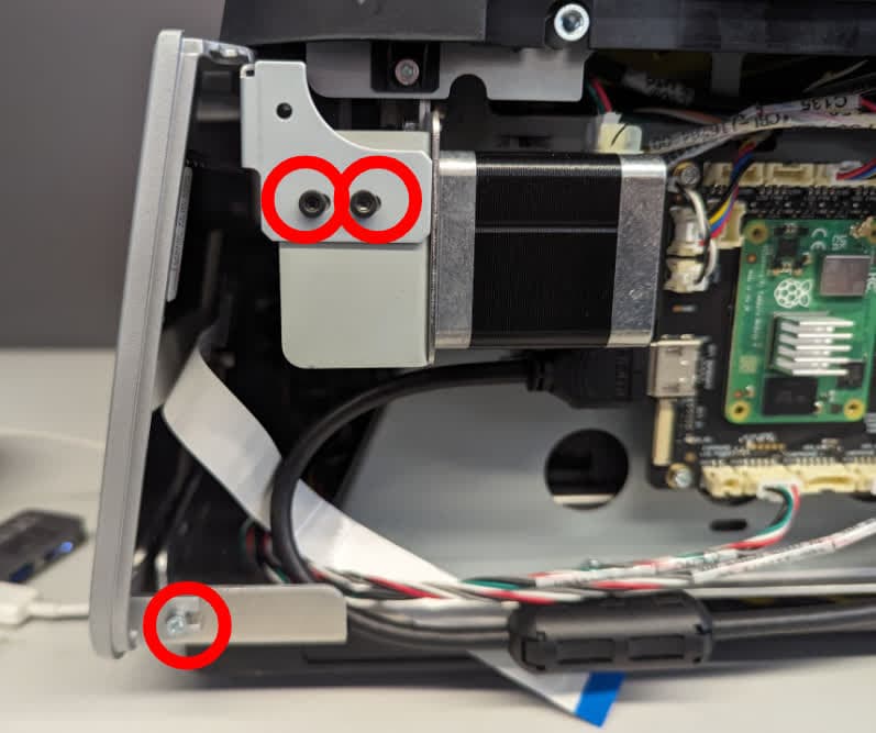
使用 2.5mm 六角扳手,拧下将右侧触摸屏组件固定到打印机上的 3 颗螺丝。将螺丝放在一旁。
第 5 步:旋转打印机
合上打印机机罩,小心地将打印机背面朝上放置。
第 6 步:拧松底部面板螺丝
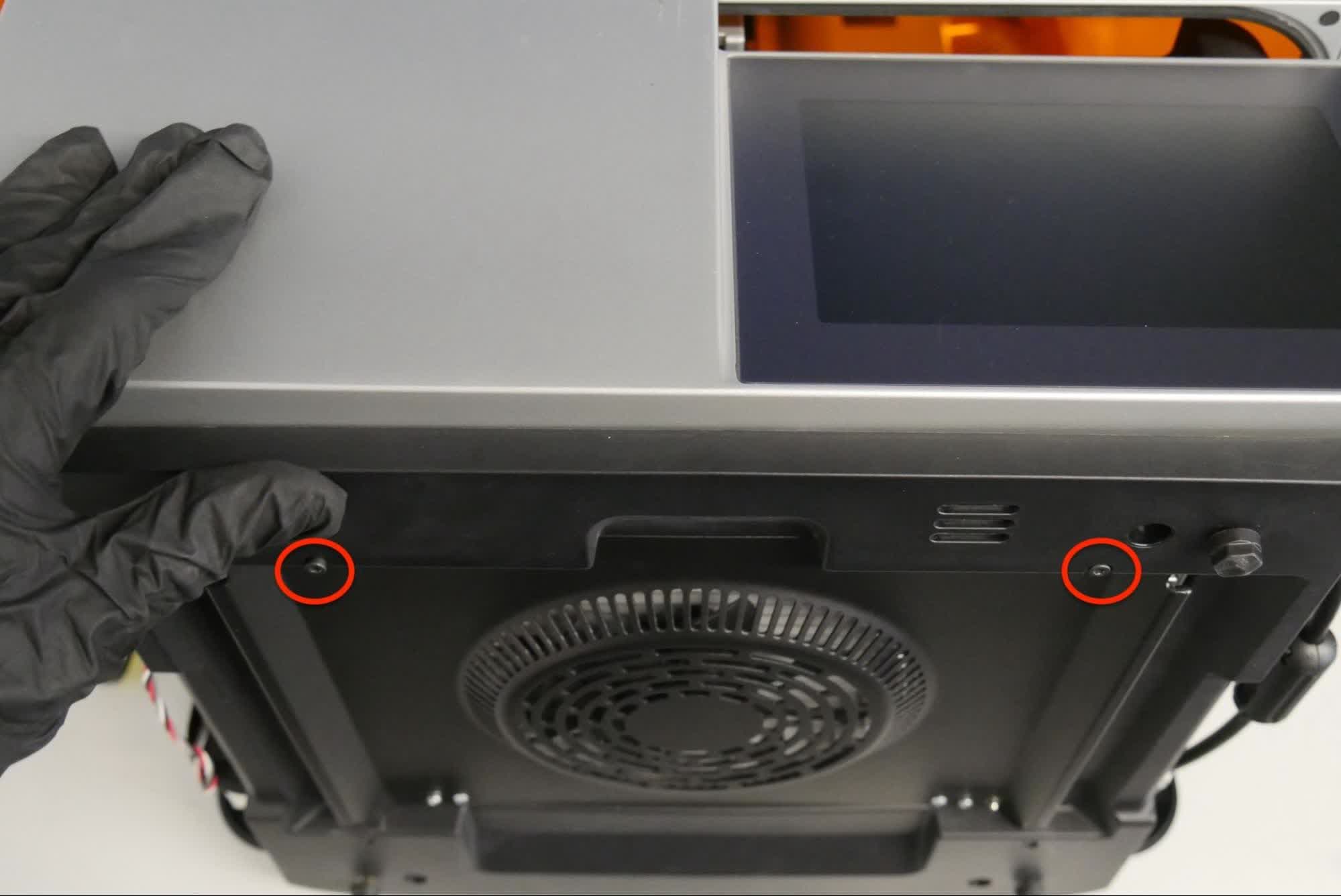
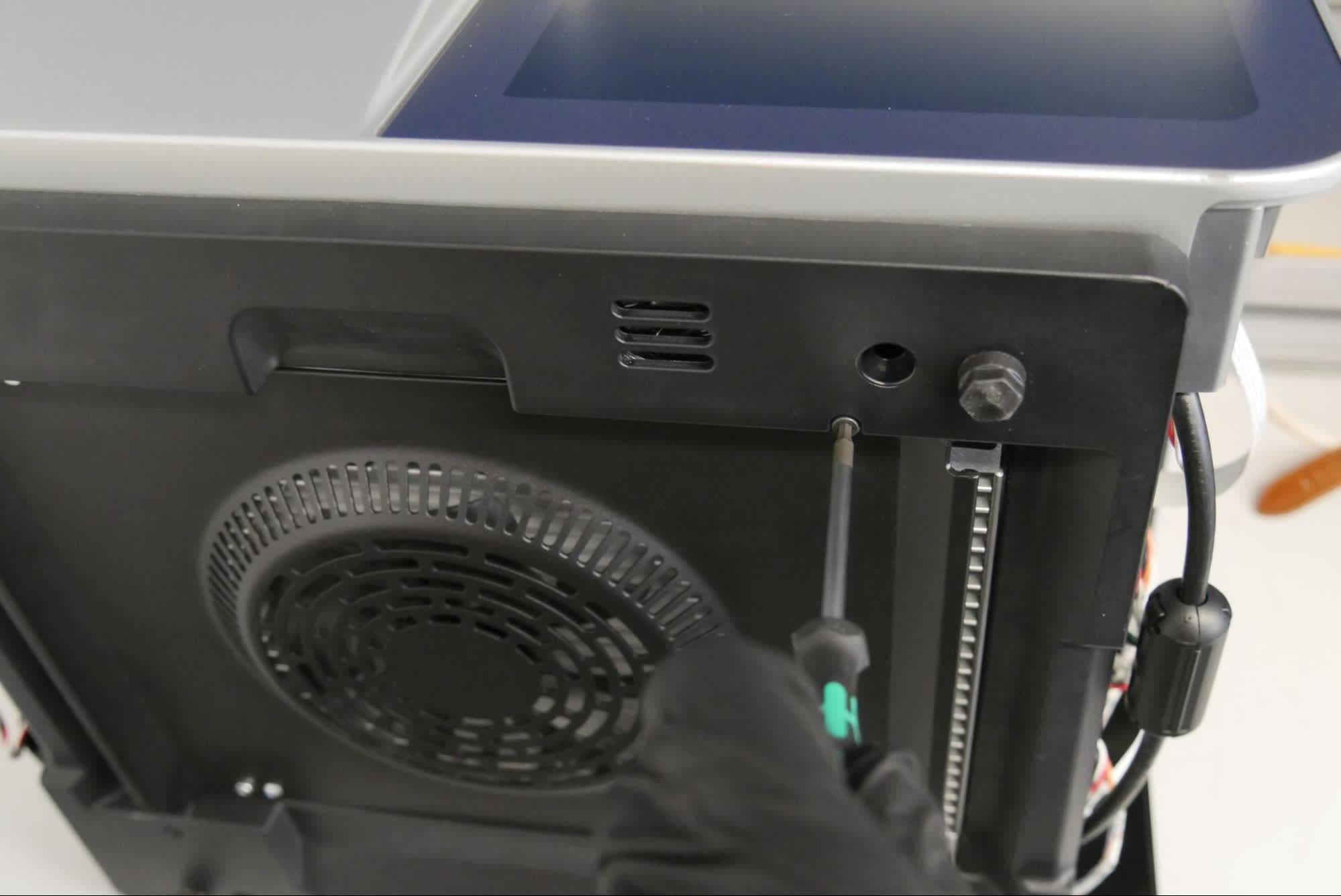
使用 2.5mm 六角扳手拧松固定底部面板的两颗螺丝。请勿完全拧下螺丝。
第 7 步:找到底部插片
将底部面板从打印机上轻轻拉开,露出触摸屏组件的两个底部插片。如果无法看到插片,则进一步拧松底部面板的两颗螺丝。
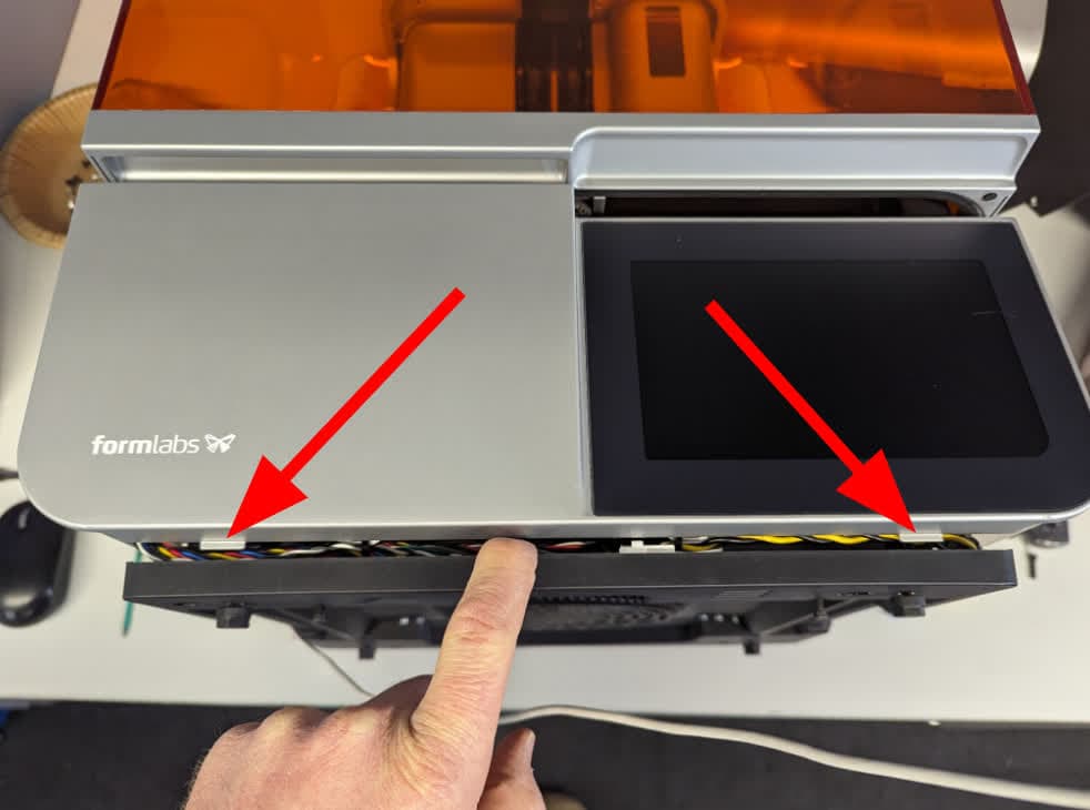
第 8 步:拆卸触摸屏组件
握住触摸屏组件的底角。小心地将触摸屏组件拉向您的方向。触摸屏组件的底部与打印机紧密贴合,可能需要额外施力才能取下。旋转触摸屏组件,直到可以看到其背面。在触摸屏带状电缆断开之前,请勿拉离打印机。
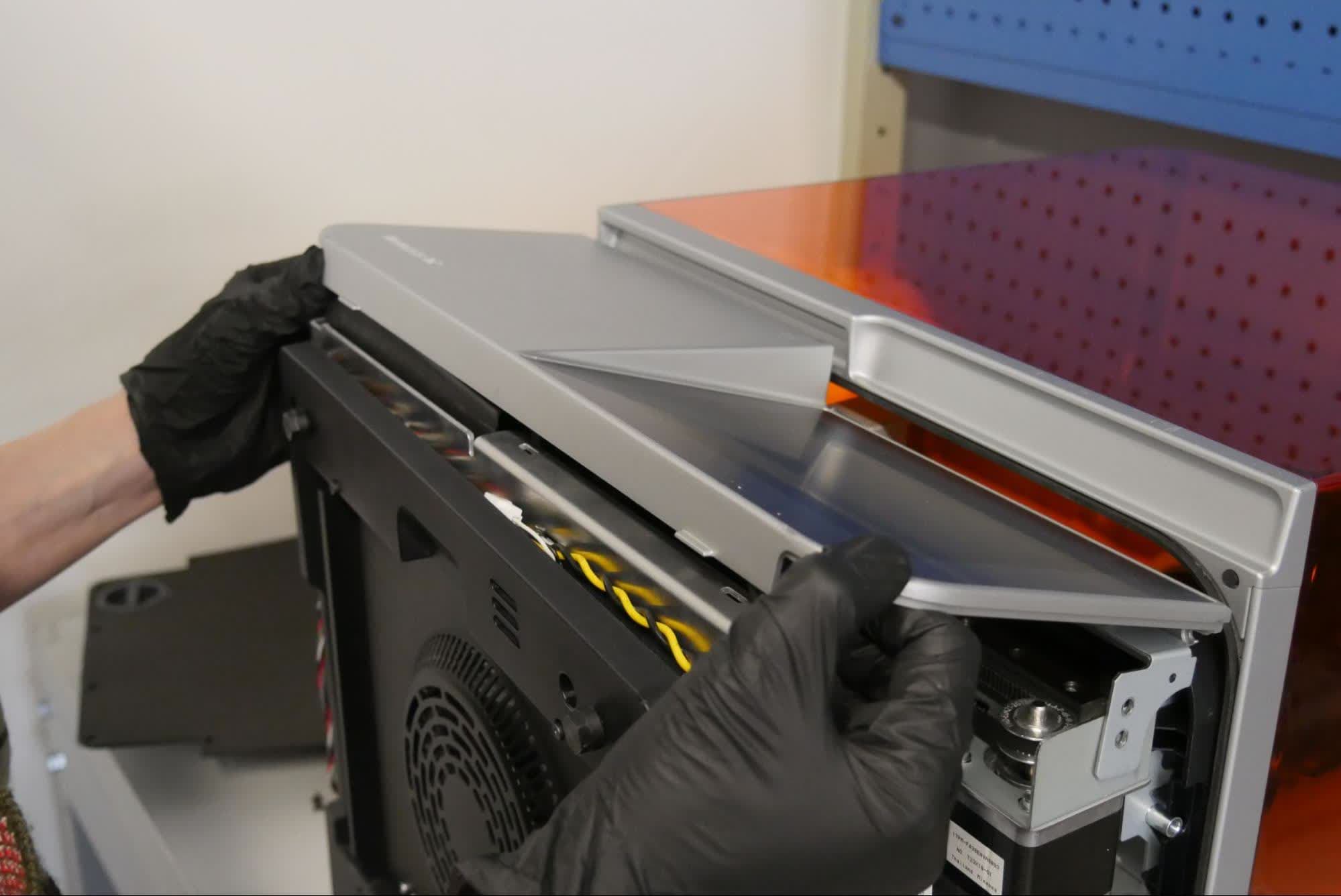
第 9 步:断开触摸屏带状电缆
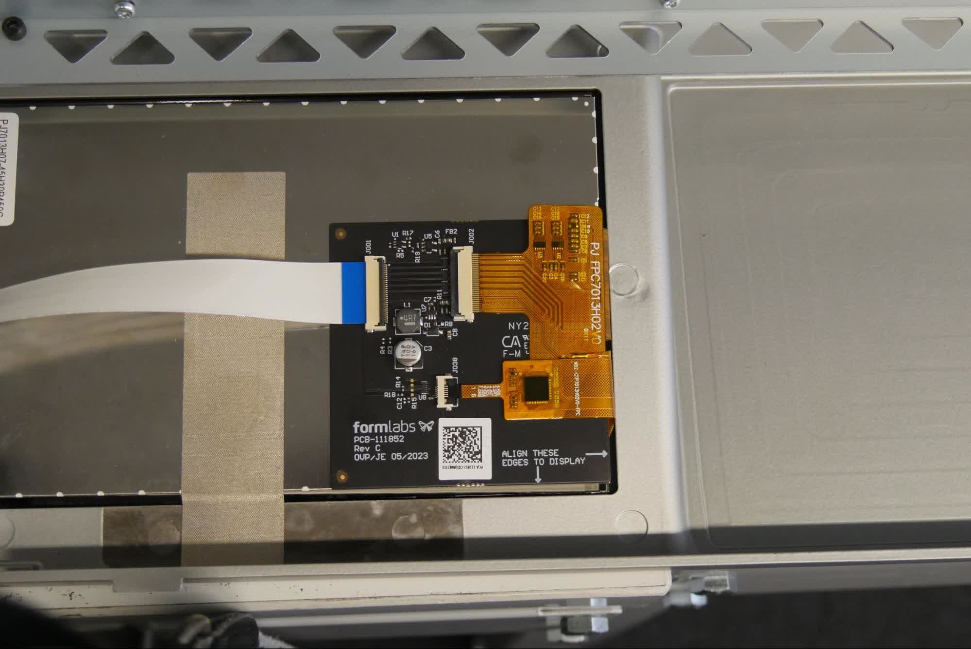
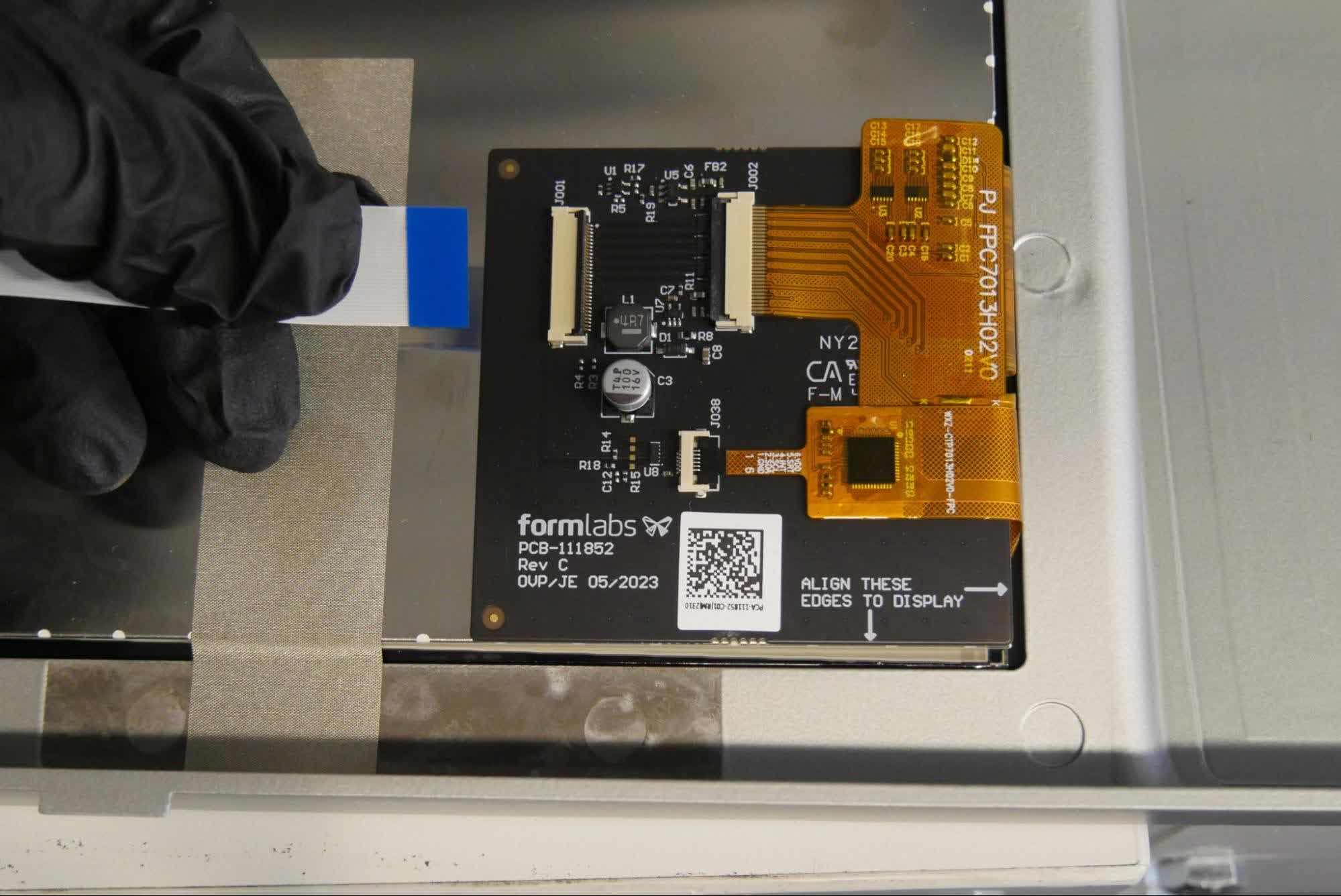
将连接器上的黑色塑料插片旋转到远离触摸屏组件的位置,松开触摸屏带状电缆。请勿拉动电缆。一旦正确松开黑色插片,以最小的力即可将电缆从连接器中滑出。将显示器组件放在一旁。
移除 嵌套
概览: 拆卸 LPU 后, 嵌套。
第 1 步:拧下侧面螺丝
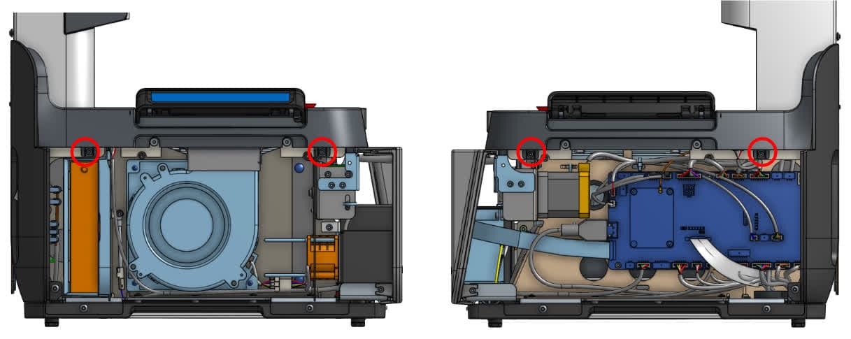
打印机的左右两侧各有两颗侧面螺丝,用于将组件仓固定在打印机上。使用 2.5mm 六角扳手 拧下侧面螺丝将螺丝放在一旁。
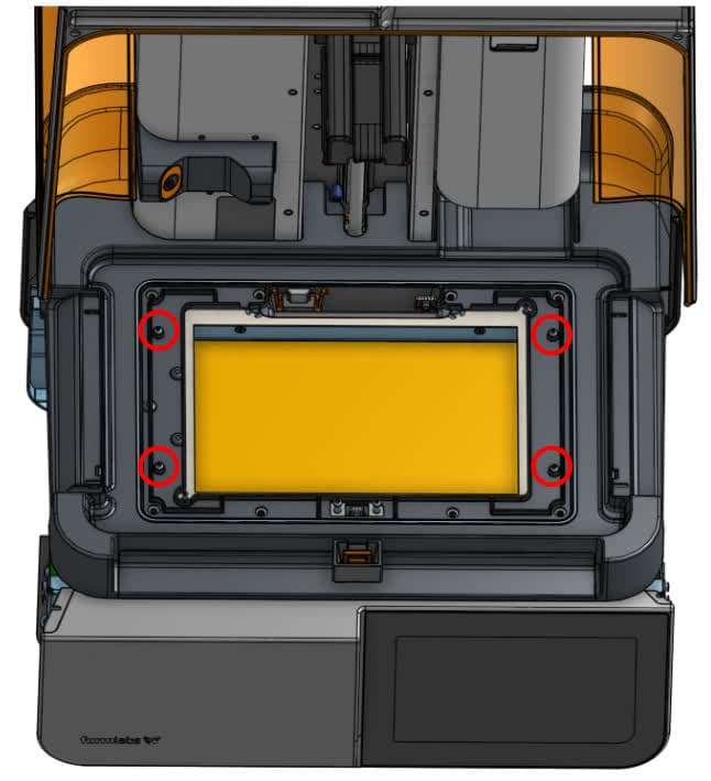
Use a 2 mm hex driver to remove the four screws on the top of the nest. Set the screws aside.
注意:
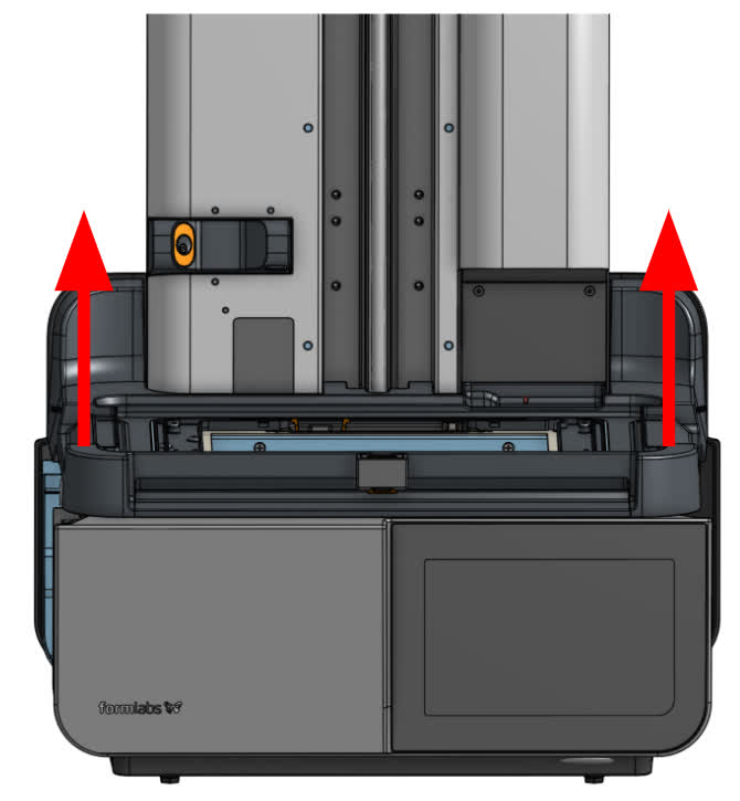
取出打印板底座时请小心,并确保解开电缆。拔出电缆时要小心,以免损坏。按下塑料插片后,电缆应能轻松滑出连接器。请勿拉扯电线。
第 4 步:断开互锁电缆
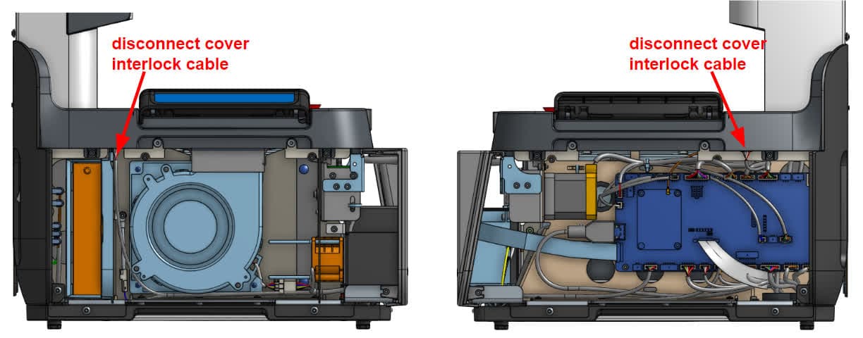
拔下连接到组件仓的机罩互锁板上的电缆。将组件仓放在一旁。
拆卸下部后面板
概览: 取下 支架上,拆下下部后面板。
第 1 步:拧下侧面螺丝
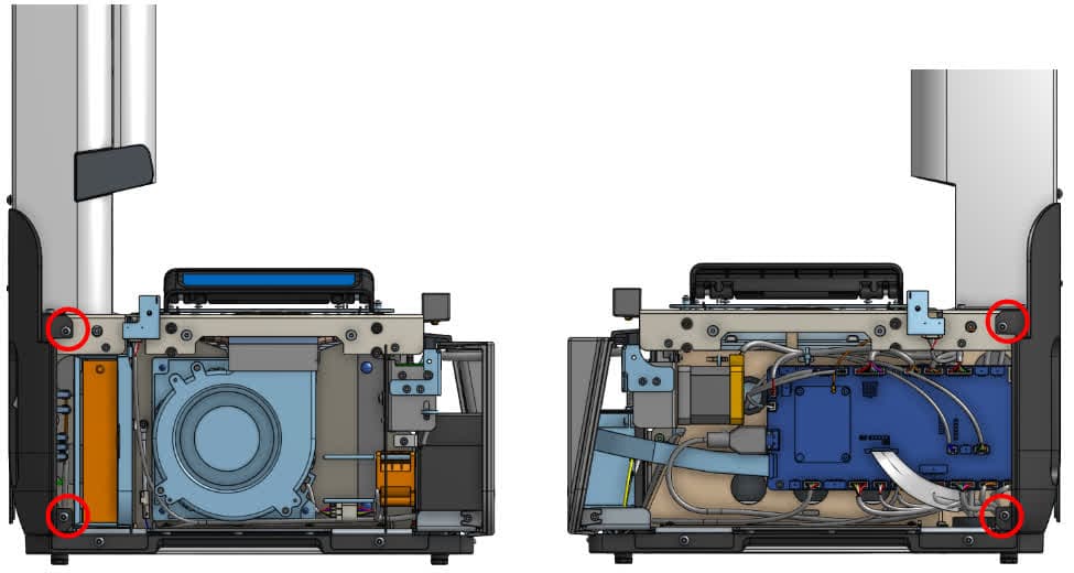
使用 使用 2.5mm 六角扳手,拧下将下部后面板固定在打印机上的两颗左侧螺丝和两颗右侧螺丝。将螺丝放在一旁。
使用 2.5mm 六角扳手,拧下将下部后面板固定在打印机上的四颗螺丝。将螺丝放在一旁。
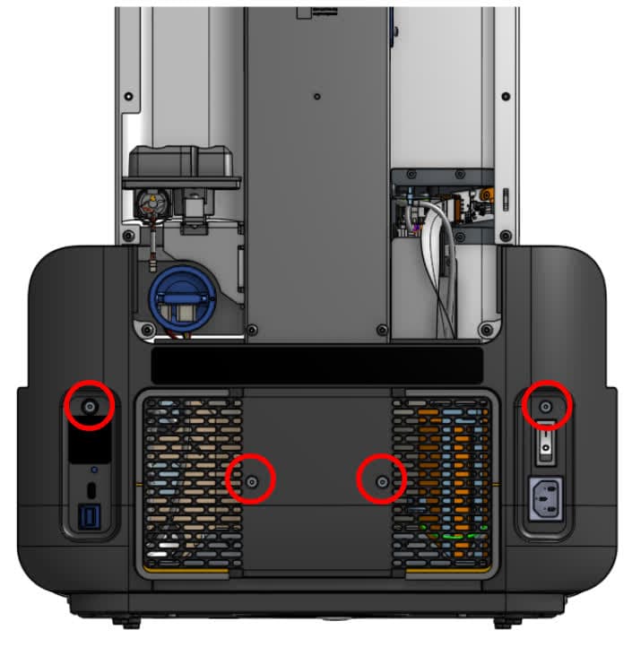
第 3 步:拆卸下部背板
拆卸下部后机罩并放在一旁。
移除 主板
Overview: After removing the exterior panels, remove the motherboard.
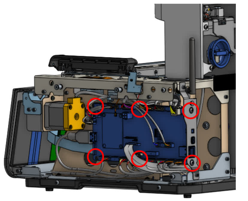
警告:
拔出电缆时要小心,以免损坏。按下塑料插片后,电缆应能轻松滑出连接器。请勿拉扯电线。
安装主板替换件
概览: 拆卸旧的 主板,连接并安装替换件。
第 1 步:安装主板安装螺丝
Position the motherboard on the right side of the printer so the screw holes are aligned. Using a 2.5 mm hex driver, install the four hex screws on the left side of the motherboard. Using a 2 mm hex driver, install the two hex screws on the back of the printer. Do not overtighten the screws.
Step 2: Connect the cables to the motherboard
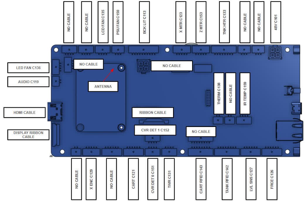
将所有电缆重新连接至主板。使用新 编号 电缆上的标签与 标签 打印机的序列号
安装下部后面板
概览: 更换 主板后,安装下部后面板。
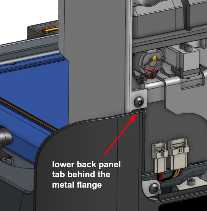
第 1 步:放置面板
对齐下部后面板。确保主板端口、电源开关和电源插座与下部后面板的相应插槽对齐。确保下部后面板顶部的两个插片位于塔板金属法兰的后面。
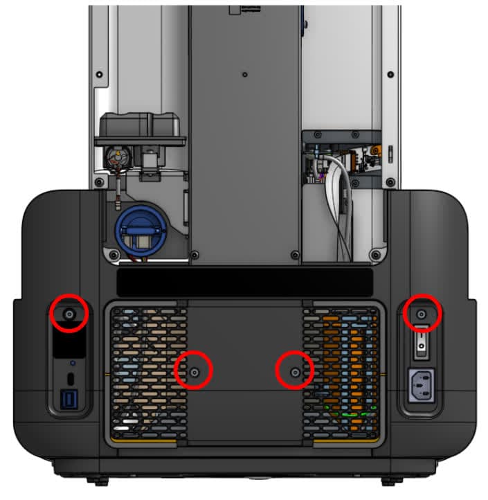
第 2 步:安装后部螺丝
使用 2.5mm 六角扳手,安装将下部后面板固定到打印机上的 4 颗螺丝。拧紧螺丝,直至其紧固到位。
第 3 步:安装侧面螺丝
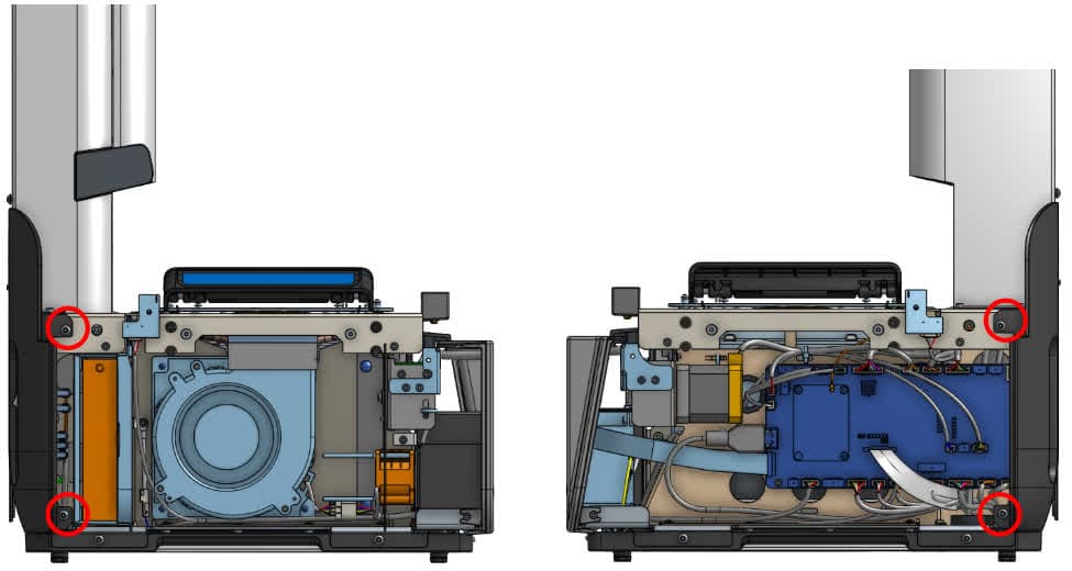
使用 使用 2.5mm 六角扳手,安装将下部后面板固定在打印机上的两颗左侧螺丝和两颗右侧螺丝。
安装组件仓
概览: 安装好下部后面板后,安装 嵌套。
第 1 步:放置网笼
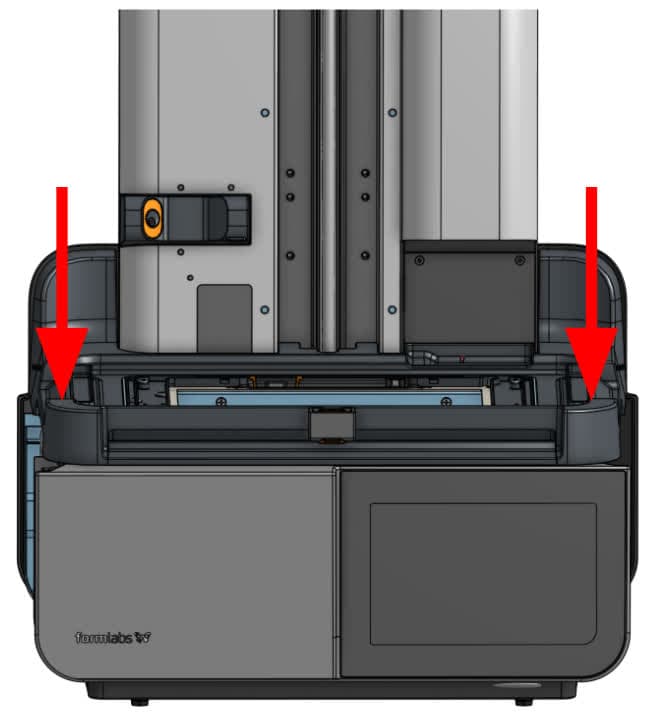
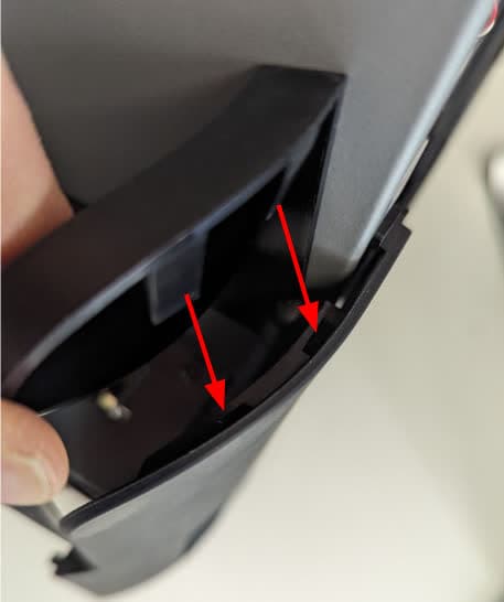
将打印机 将其放置在打印机上 注:前缘有垫圈,会产生一些阻力。确保打印机后部的法兰 将打印机的下部面板放在打印机的下部面板上。
使用 2mm 六角扳手安装 四个 打印机顶部的螺丝 嵌套。拧紧螺丝,直至 拧紧螺丝
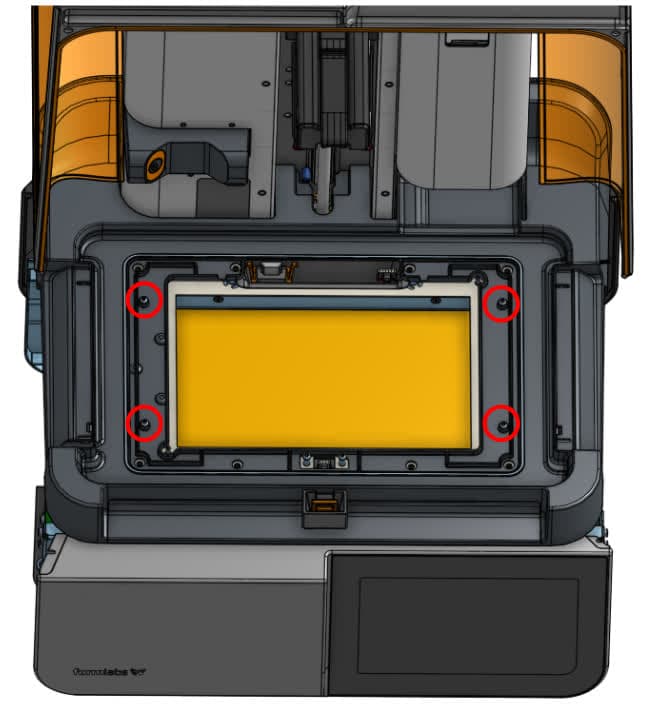
第 3 步:安装侧面螺丝
使用 2.5mm 六角扳手,安装固定左侧和右侧的两颗螺丝 打印机的打印平台上
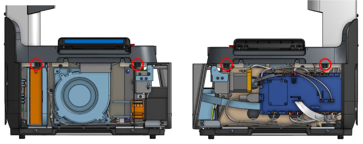
第 4 步:连接机罩互锁电缆
将打印机两侧的机罩互锁电缆 嵌套。塑料插片应卡入到位,以固定连接。
重新安装触摸屏组件
概览: 安装好打印机底座后,重新安装触摸屏组件。
第 1 步:将触摸屏带状电缆连接到显示屏组件上
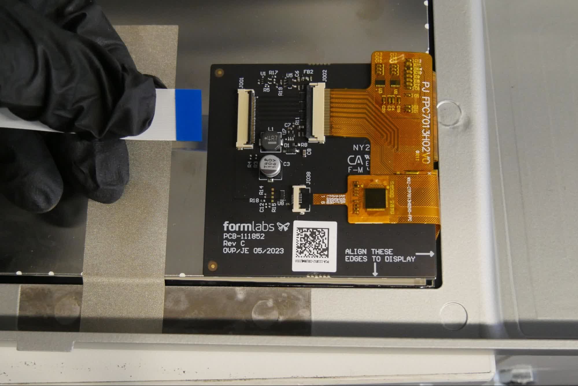
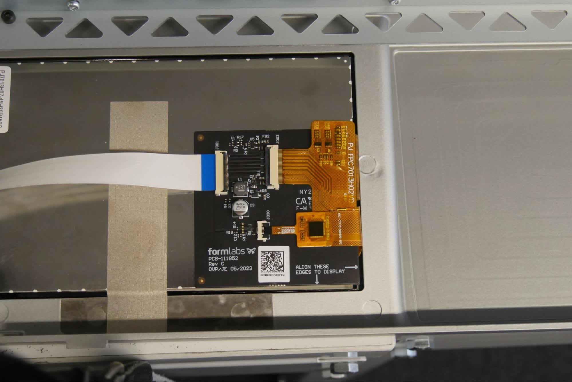
将带状电缆滑入触摸屏组件上的连接器。确保电缆均匀插入。蓝色标记应朝上。
第 2 步:固定带状电缆
向下翻转连接器上的黑色插片,将电缆固定到触摸屏组件上。安装时注意切勿拉扯电缆。
第 3 步:放置触摸屏组件以便安装
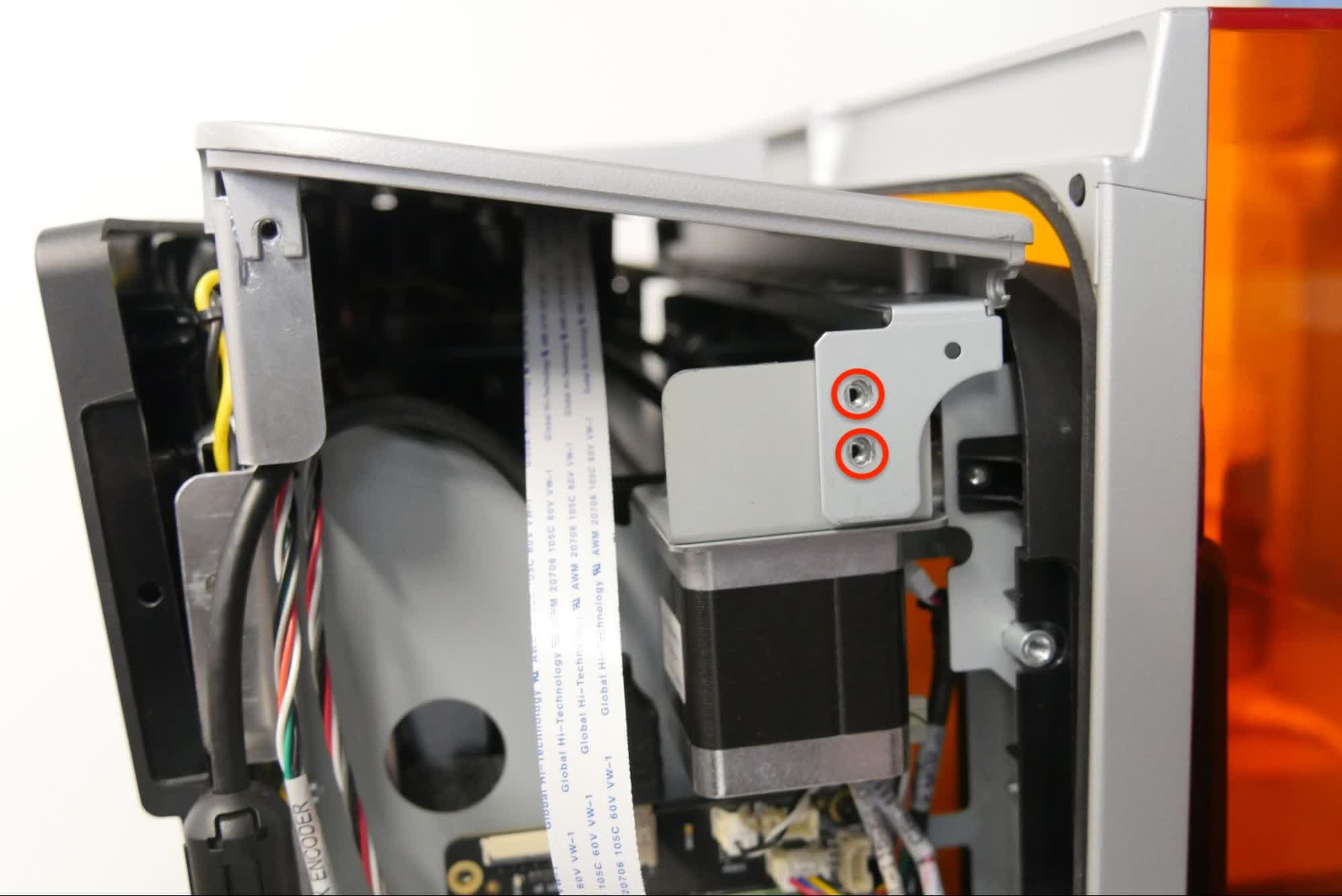
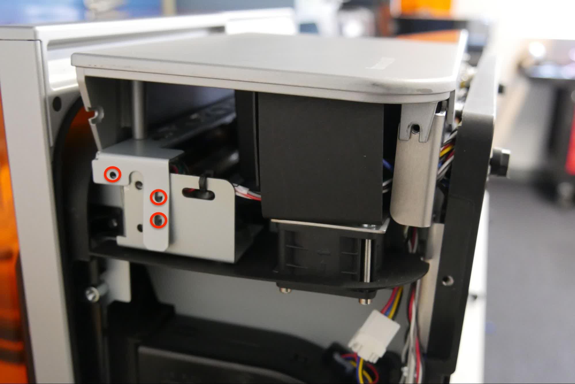
Position the touchscreen assembly on the printer. Make sure that the sheet metal tabs are positioned outside of the printer frame and that they align with the screw holes on the printer. Take care not to crush or fold the touchscreen ribbon cable.
Step 4: Tighten the bottom panel screws
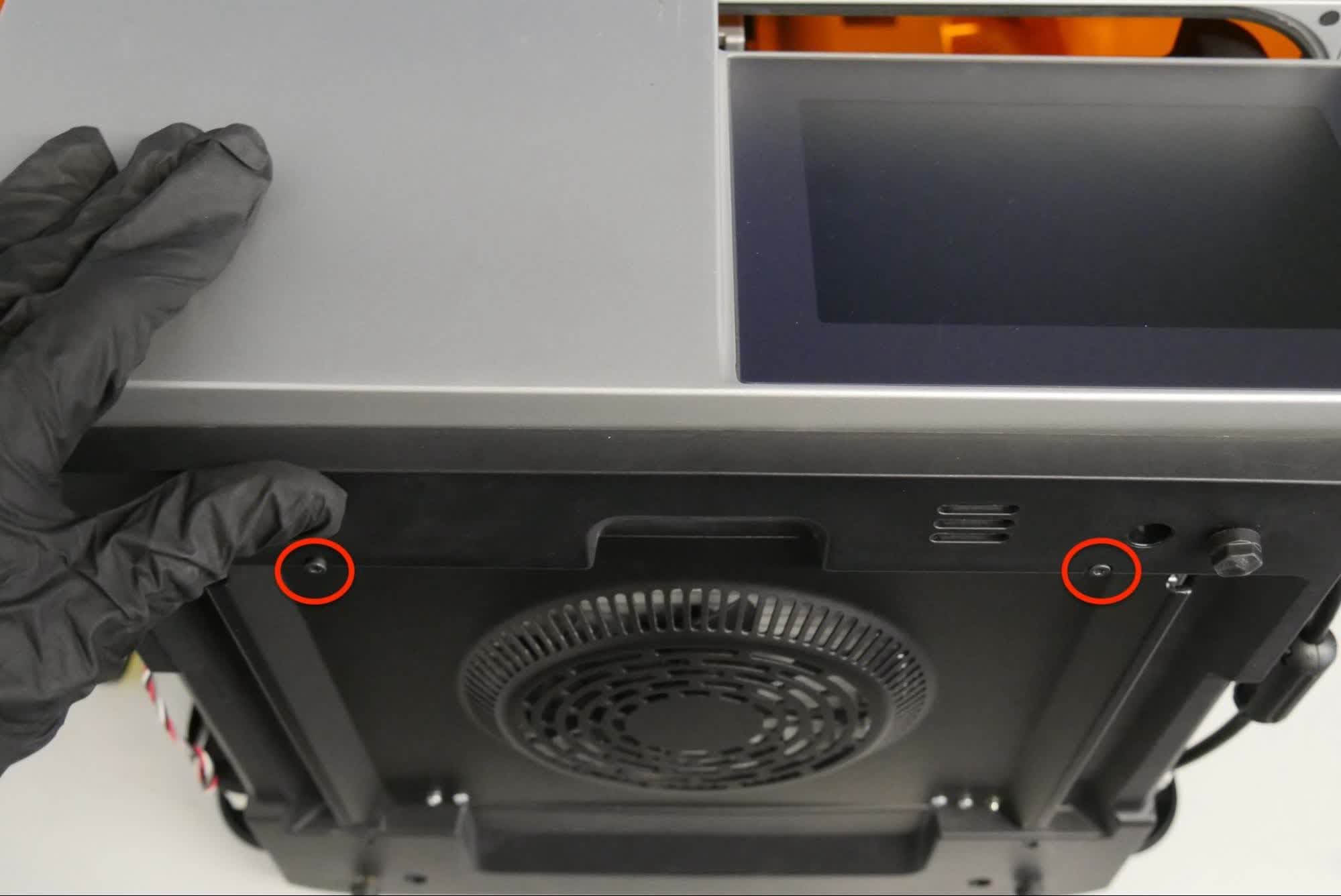
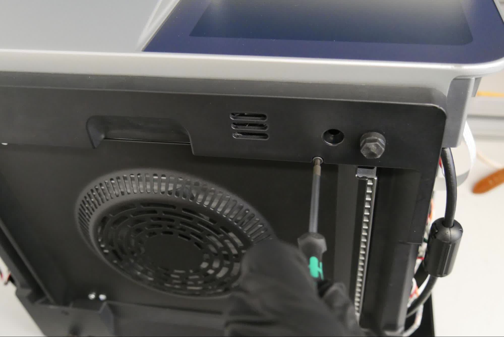
Make sure that the two bottom tabs of the touchscreen assembly can slide into the printer before tightening the screws. Use a 2.5 mm hex driver to tighten the two screws that secure the bottom panel to the printer.
Step 5: Set the printer upright
Rotate the printer to sit upright.
Use a 2.5 mm hex driver to install the three screws securing the right side of the touchscreen assembly to the printer. Tighten the screws until snug.
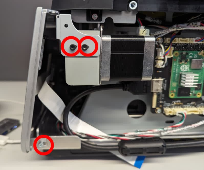
第 7 步:重新连接触摸屏带状电缆
将触摸屏带状电缆重新连接至主板。确保插入均匀。蓝色标记应朝外。向下翻转连接器上的黑色插片,将电缆固定到其连接器上。安装时注意切勿拉扯电缆。
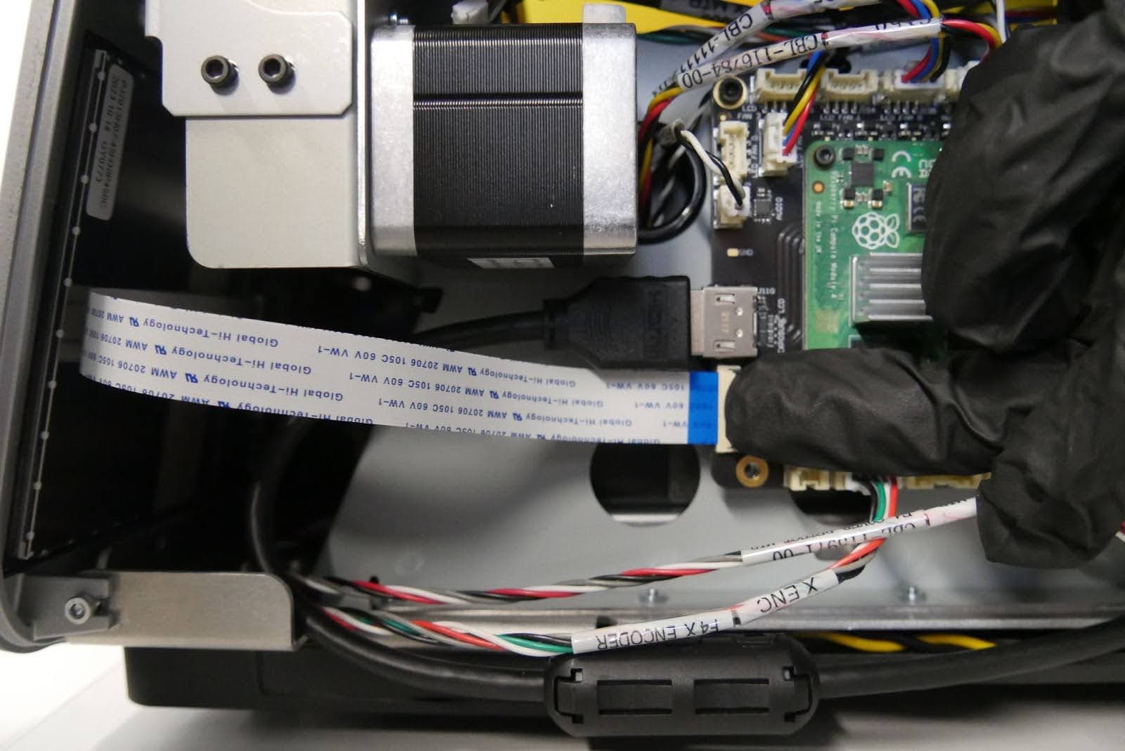
第 8 步:安装左侧触摸屏组件螺丝
使用 2.5mm 六角扳手,安装将左侧触摸屏组件固定到打印机上的 3 颗螺丝。拧紧螺丝,直至其紧固到位。
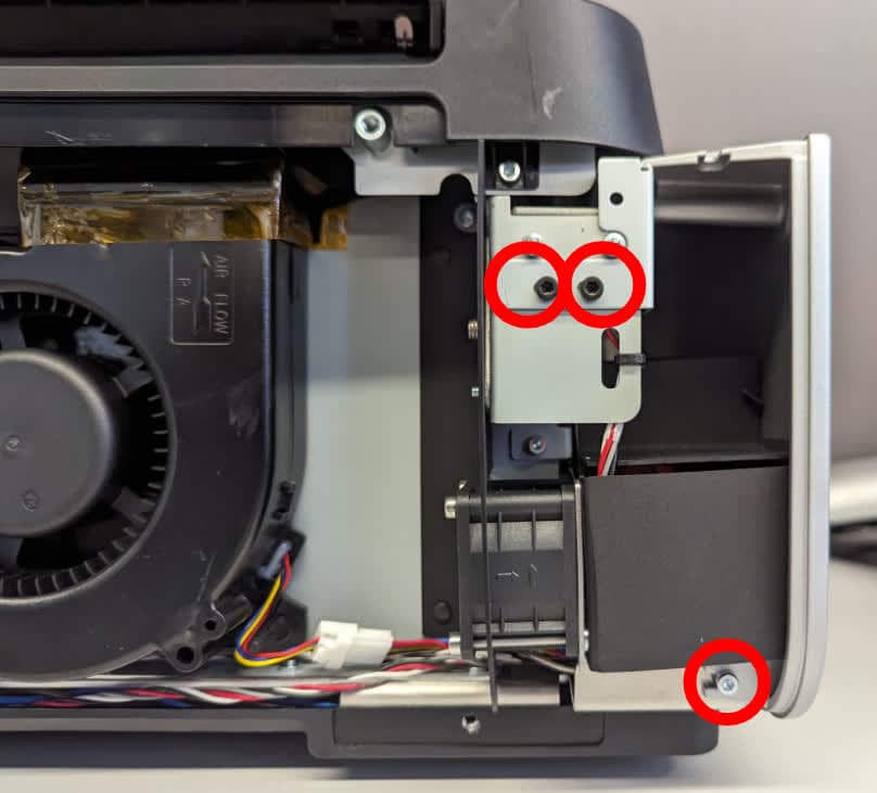
重新安装树脂槽锁销
Overview: After reinstalling the touchscreen assembly, reinstall the resin tank latches.
Step 1: Pre-assemble the resin tank latch
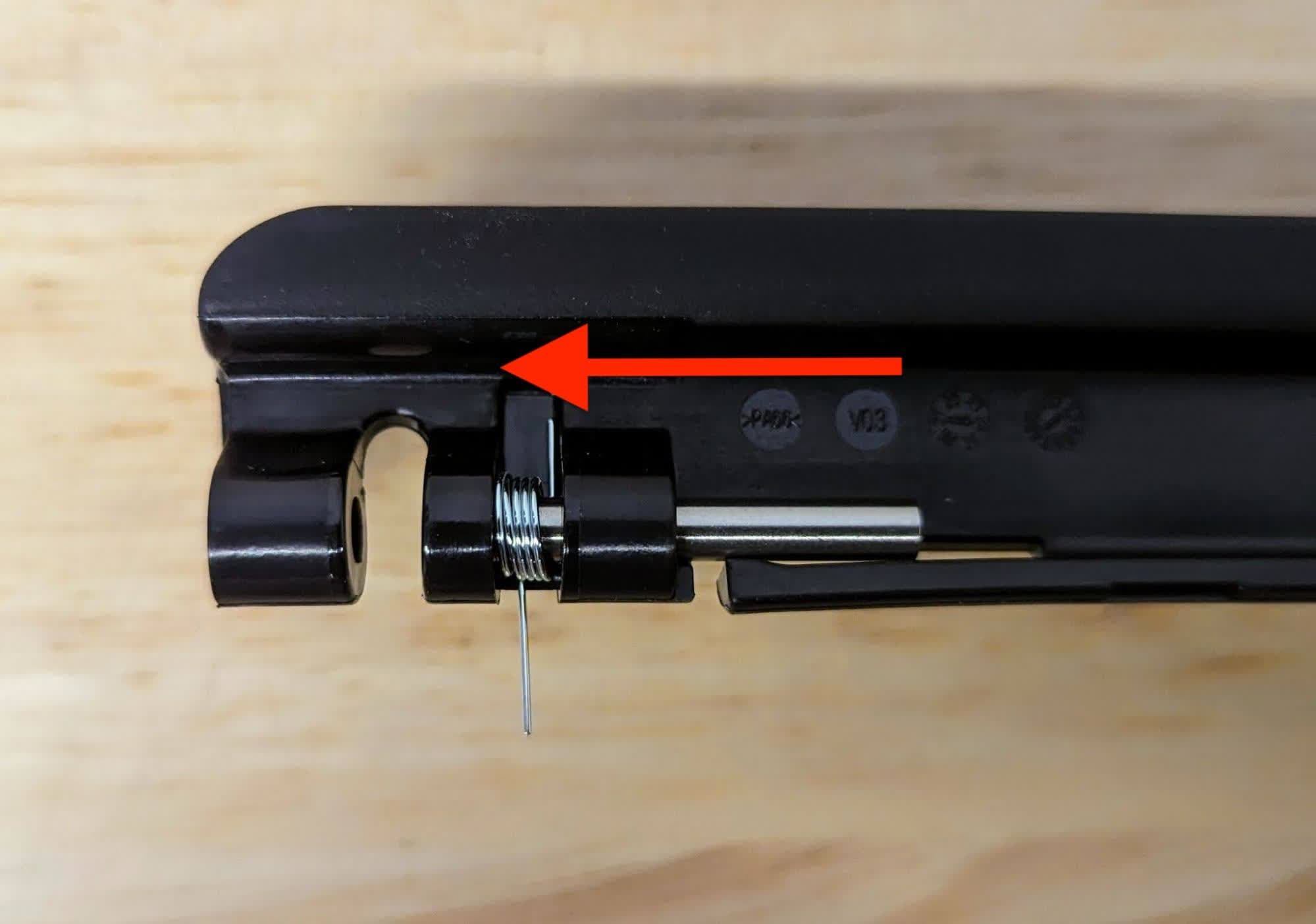
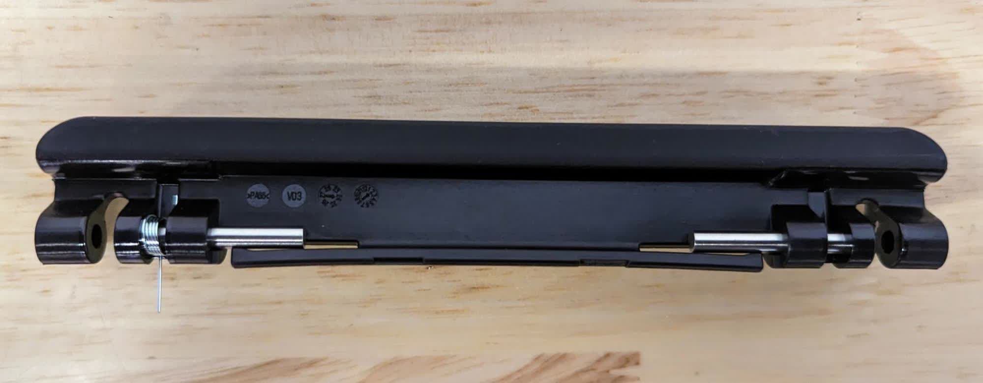
The resin tank latch needs to be partially assembled before installing it onto the printer. Slide the metal pins into the bracket from the inside of the latch. Insert the spring as shown with the shorter leg pressed against the latch. The pin threads through the spring. Leave space in the bracket for installation.
Repeat the previous step to thread the pin through the second bracket. Note that there is only one spring per latch, and the spring should be positioned such that it will be towards the front of the printer once the latch is installed.
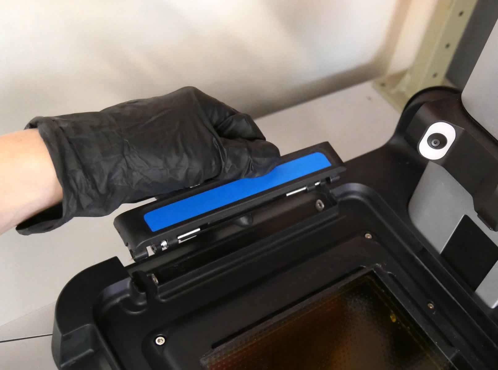
Align the resin tank latch with the pins and spring facing towards the LPU.
第 3 步:安装树脂槽锁销
将锁销下放到位,确保较长的弹簧脚位于打印机前方的小孔中。可轻松安装手柄,几乎无需费力。
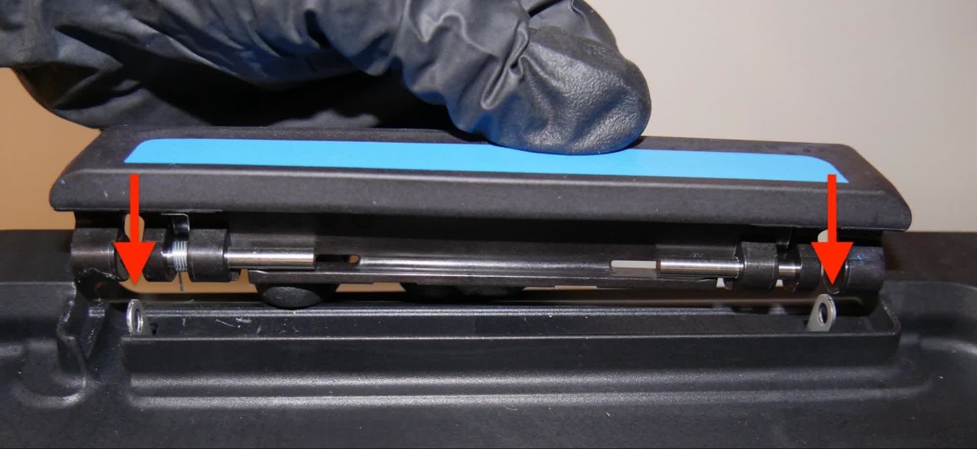
第 4 步:安装销钉
根据需要调整锁销,使销钉与金属插片对齐。使用 2.5mm 六角扳手压住固定插片。使用 2mm 球头六角扳手将销钉推入支架。可能需要使用适度的力来使销钉就位。当固定插片卡入销钉后面时,销钉即完全就位。
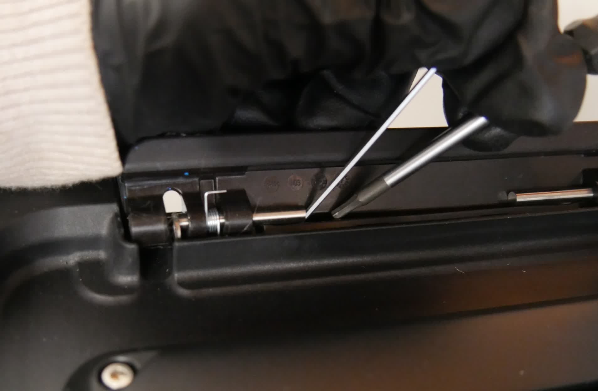
Step 5: Install the second pin
Repeat the previous step to install the second pin in the resin tank latch. Note that there is only one spring per latch, located towards the front of the printer.
Step 6: Repeat
Repeat steps 2-4 on the second resin tank latch.
Reinstalling the LPU
Overview: After replacing the motherboard, connect and reinstall the LPU.
Step 1: Connect the tank heater cable
Position the LPU so the connector ports are oriented towards the back of the printer. Plug the tank heater cable into the connector on the LPU. The plastic tab should click into place to secure the cable.
Step 2: Connect the HDMI cable
Plug the HDMI cable into the port on the LPU. Ensure that the two prongs on the plastic retaining clip snap into place.
Step 3: Mount the LPU
Ensure that the optical cavity and LPU are free from dust and debris. Place the LPU onto the optical cavity and align the screw holes.
第 4 步:拧入外壳螺丝
使用 2.5mm 六角扳手部分拧紧 LPU 外壳上的八颗六角螺丝。
第 5 步:固定 LPU
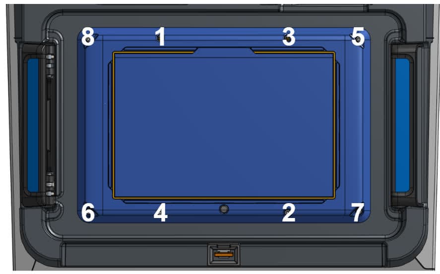
松装所有螺丝后,按对角线方式拧紧螺丝,如上图所示。螺丝应牢固,但不能过紧。为避免过度拧紧,请握住六角扳手的短端。
重新安装外部面板
Overview: Install the left, right, and upper back exterior panels. Also install the rear mesh filter.
Step 1: Reinstall the rear mesh filter
Reattach the mesh filter to the printer, ensuring that it is aligned with the air intake vents.
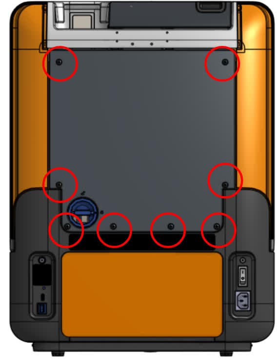
Slide the back cover into place on the back of the printer. Using a 2.5 mm hex driver, install the eight screws that secure the back panel to the printer. Tighten the screws until snug.
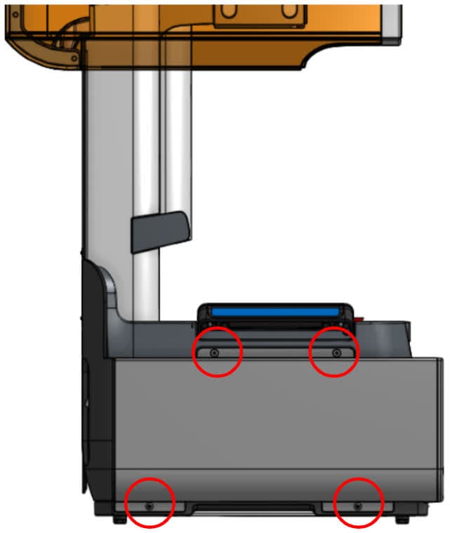
第 3 步:安装左侧面板螺丝
使用 2.5mm 六角扳手,安装将左侧外部面板固定到打印机上的 4 颗螺丝。拧紧螺丝,直至其紧固到位。
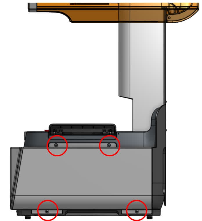
第 4 步:安装右侧面板螺丝
使用 2.5mm 六角扳手,安装将右侧外部面板固定到打印机上的 4 颗螺丝。拧紧螺丝,直至其紧固到位。
完成修复
Overview: After installing the new motherboard, power on the printer and perform final checks.
Step 1: Power on the printer
Close the printer cover and connect the power cable to the printer and the power supply. Turn on the switch at the back of the printer. The printer turns on and initializes.
Step 2: Run the Align build platform calibration
From the printer touchscreen, select Settings > Tools > Align build platform and follow the on-screen instructions.
Step 3: Re-activate biocompatible license (Form 4B customers only)
After the motherboard replacement, the biocompatible license will be temporarily disabled. Connect the printer to the internet to automatically refresh the license.
Step 4: Run a test print
Insert any missing consumables and upload and start a print. Check that the print starts normally and the parts print successfully. Contact Formlabs Support or your authorized reseller to share the results of the procedure.