注意:
使用打印设置编辑器或任何第三方材料均存在风险,包括打印机损坏风险。请阅读服务条款,了解相关风险。

PreForm 打印设置编辑器通过自定义一系列打印设置(控制激光功率、速度、运动和粉末加热),支持用户定制 Formlabs 材料和经供应商认证的第三方材料的打印性能。只有了解如何修改打印参数和调试打印问题的高级用户才能使用该工具。如果在使用自定义打印设置进行打印时出现问题,Formlabs Support 将要求您恢复为 Formlabs 默认打印设置。鉴于自定义打印设置的复杂性,我们无法协助您进行微调或开发自定义打印设置。
注意:
使用打印设置编辑器或任何第三方材料均存在风险,包括打印机损坏风险。请阅读服务条款,了解相关风险。
注:
PreForm 3.41.0为 Formlabs SLS 打印机引入了打印设置编辑器。随时更新 PreForm,以获取最新的打印准备功能。
调试简介
调试属于多参数优化问题。在更改一个参数时,往往也需要更改其他参数。例如,如果增加周长激光功率,则可能需要调整周长到填充间距,以保持小型特征的尺寸精度不变。
打印性能在很大程度上取决于模型几何形状以及定向方式。您可以创建自定义打印设置,但该设置并不适用于所有模型。如果计划经常使用自定义打印设置,请确保使用各种模型对自定义打印设置进行测试。
维护打印机正常运行
注意:
某些参数设置组合会导致打印失败或打印机损坏,包括但不限于产生烟雾、粉末燃烧和大面积粉末熔化。在使用 Formlabs SLS 打印机的打印设置编辑器之前,请阅读并理解以下指南。
创建自定义打印设置
| 基于 Formlabs 打印设置 | 基于自定义打印设置 |
|---|---|
|
|
编辑自定义打印设置
提示:
导出自定义打印设置
导入自定义打印设置
删除自定义打印设置
提示:
要快速删除所有自定义打印设置,请单击打印设置编辑器界面顶部的 Delete All(全部删除)。随即显示确认窗口。单击 Delete All(全部删除) 以确认并删除所有自定义设置。
使用自定义打印设置打印
可用参数
Fuse 1 代
注:
该部分正在开发中。内容可能会更改。
| Name | Description | Units | Reasons to Modify | Common Issues |
|---|---|---|---|---|
| Layer Thickness | Thickness of a single layer of powder during printing. | mm | To adjust print speed, surface finish, or Z-axis fine feature performance. Increasing this value can improve print speed. Decreasing this value can improve surface finish or fine feature resolution. | Most parameters are tuned around layer thickness. If you change layer thickness, you need to adjust almost every other parameter to get optimal print results. |
| X Correction Factor | Scale factor for the X axis to account for print scale correction. | unitless | To adjust dimensional accuracy of large features (larger than several millimeters) in the X direction. This value is preset by Formlabs to compensate for the volumetric shrinkage of each Formlabs material. | |
| Y Correction Factor | Scale factor for the Y axis to account for print scale correction. | unitless | To adjust dimensional accuracy of large features (larger than several millimeters) in the Y direction. This value is preset by Formlabs to compensate for the volumetric shrinkage of each Formlabs material. | |
| Z Correction Factor | Scale factor for the Z axis to account for print scale correction. | Array field of Z positions, with unitless scale factors |
The Z Correction Factor array field defines a lookup table of Z height (mm) and scale factors. With one entry, it acts as a constant correction. With multiple entries, it linearly interpolates between them. Click Edit Array Field to open the table popup, where you can add, duplicate, edit, or delete points in the lookup table. 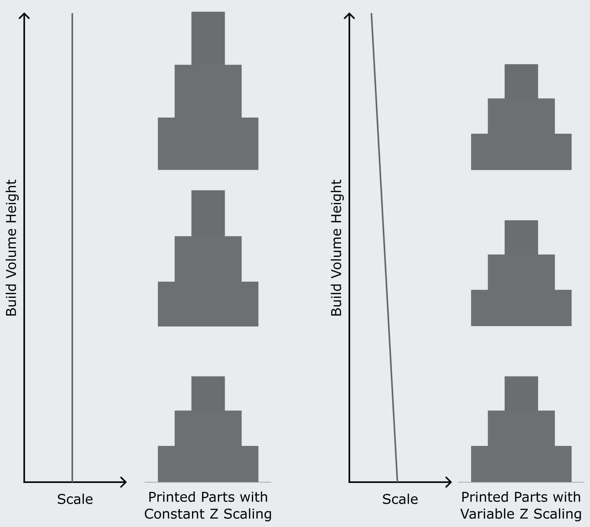
To paste data, use Ctrl/Cmd+P or the Paste button. You can paste 2-column tab-separated values copied from a spreadsheet (e.g., Google Sheets or Excel) or a JSON array of pairs (e.g., [[0, 1.0], [10, 1.1]]). The format is detected automatically. To copy data, use Ctrl/Cmd+C or the Copy button. This exports the table as tab-separated values. | |
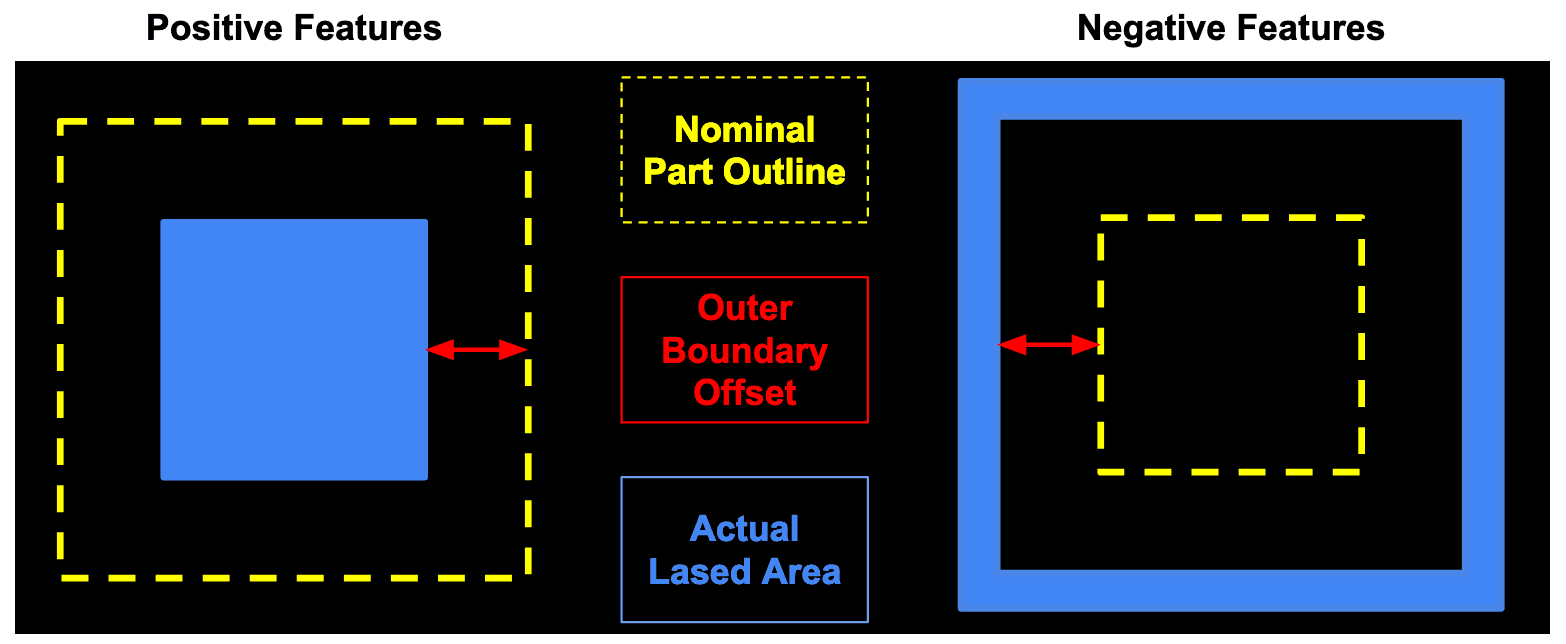
| Outer Boundary Offset | The space between the outermost perimeter laser path and the model's nominal boundary. A positive value means the laser perimeter will be inset smaller than the model's nominal boundary. | mm |
To correct for cases where small features (millimeter scale) are undersized or oversized.
| Changing this value too much can erode or dilate negative or positive features. For example, if you set this incorrectly, small negative holes might be filled in or small positive features might not print correctly. For additional information, see the section Visual examples of selected parameters below. |
| Fill Laser Power | Power output from the laser applied to the bulk fill of the model. | mW | To adjust energy delivery rate to the bed from the laser. Increasing this value can improve material properties. Decreasing this value can reduce dimpling and pitting defects. Overall fill laser exposure is a function of Fill Laser Power, Fill Laser Speed, and Fill Hatch Spacing. | High laser exposure can lead to surface artifacts or other symptoms of oversintering . Low laser exposure will result in brittle, weak parts and part curling. Changing the laser exposure will require tuning dimensional accuracy. |
| Fill Laser Speed | Speed the laser moves at across the bulk fill of the model. | mm/s | To adjust the laser speed at the bed. Increasing this value reduces smoking and print time. Decreasing this value can improve material properties. Overall fill laser exposure is a function of Fill Laser Power, Fill Laser Speed, and Fill Hatch Spacing . | Low laser speed (and therefore high laser exposure) can lead to surface artifacts or other symptoms of oversintering. Low laser exposure will result in brittle, weak parts and part curling. Changing the laser exposure will require tuning dimensional accuracy. |
| Fill Hatch Spacing | Spacing between adjacent scan lines within the bulk fill of the model. | mm | To change the exposure. Increasing spacing will result in more energy delivery to the print bed. Decreasing spacing will result in faster print times. Overall fill laser exposure is a function of Fill Laser Power, Fill Laser Speed, and Fill Hatch Spacing . | Close spacing (and therefore high laser exposure) can lead to surface artifacts or other symptoms of oversintering. Low laser exposure will result in brittle, weak parts and part curling. Changing the laser exposure will require tuning dimensional accuracy. |
| Upskin Layer Count | Number of layers where Upskin Laser Power is applied to the top surface of models. | layers | To change the number of layers the Upskin Laser Power parameter is applied to. | Too many upskin layers may result in Z inaccuracy or brittleness of thin parts. Too few upskin layers may result in poor top surface finish. For additional information, see the section Visual examples of selected parameters below. |
| Upskin Laser Power | Power output from the laser applied to the Upskin regions of the model. | mW |
To reduce energy delivery on top surface layers of parts. Reducing this parameter can reduce surface artifacts, such as dimpling and pitting, and make top surface finish more consistent. Note: Upskin Laser Power is applied with the Fill Hatch Spacing and Fill Laser Speed parameters. | If Upskin Laser Power is too high, top surface finish may be poor. If Upskin Laser Power is too low, thin parts may become brittle and layer delamination at the tops of parts may occur. |
| Downskin Layer Count | Number of layers where Downskin Laser Power is applied to the bottom surface of models. | unitless | To change the number of layers the Downskin Laser Power parameter is applied to. | Too many downskin layers may result in parts becoming too small in the Z direction or lead to brittleness of thin parts. Too few downskin layers may result in parts becoming too large in the Z direction. For additional information, see the section Visual examples of selected parameters below. |
| Downskin Laser Power | Power output from the laser applied to the Downskin regions of the model. | mW |
To reduce energy delivery on bottom surface layers of parts. Helps reduce downward thermal bleed and ensure correct feature size in Z. Note: Downskin Laser Power is applied with the Fill Hatch Spacing and Fill Laser Speed parameters. | If Downskin Laser Power is too high, parts may be too large in the Z direction. If Downskin Laser Power is too low, parts may become brittle or be too small in the Z direction. Layer delamination may also occur at the bottom of parts. |
| Fill Direction Rotations | Laser scan direction pattern. | Array field of layers, with angles in degrees | To change lasing direction by layer, which can improve thermal management of the build and can result in more uniform surface finish. | Some materials may exhibit increased Z-axis surface roughness when the laser fill direction is changed. Layer lines may become more apparent on vertical surfaces. |
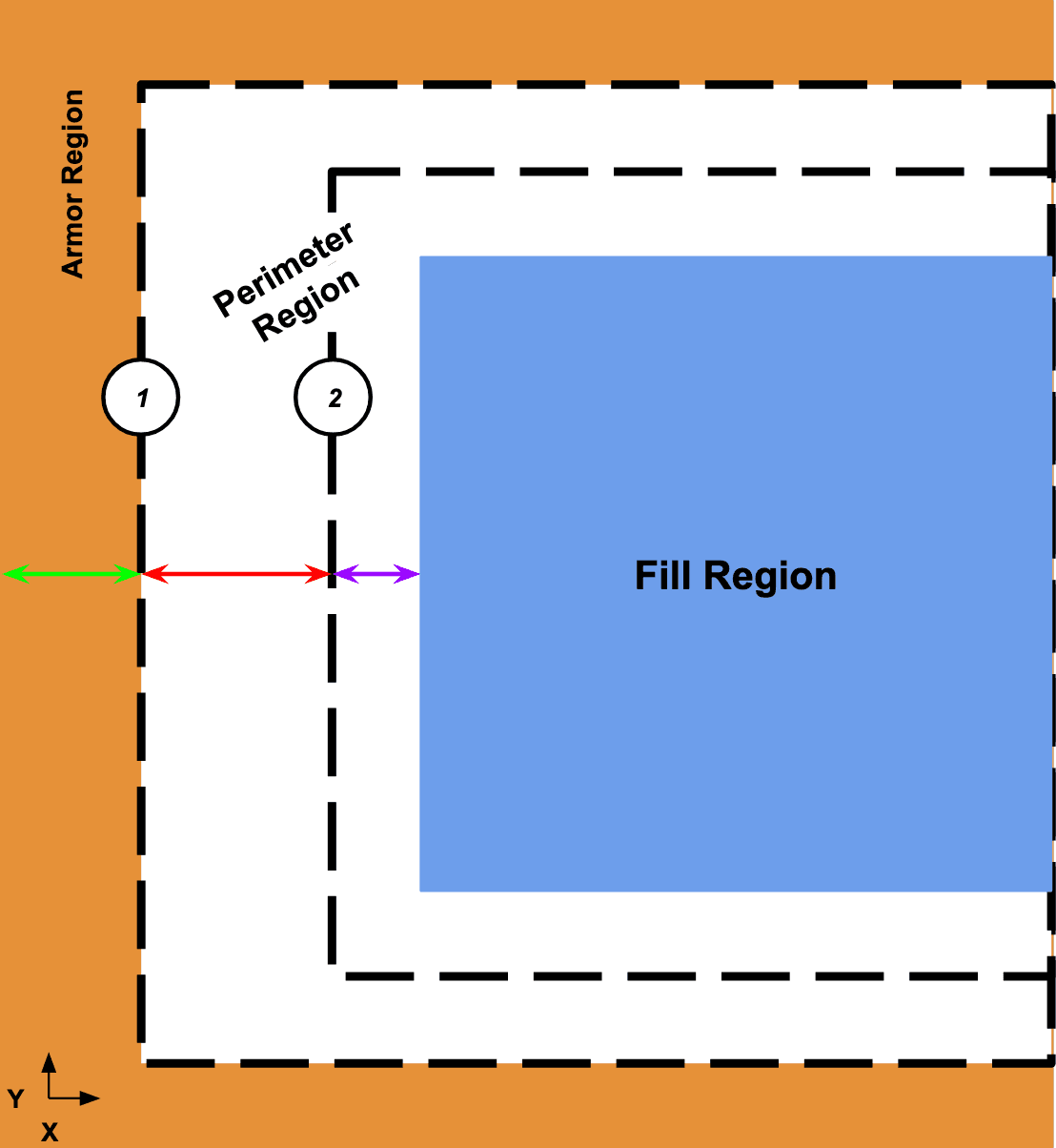
| Perimeter Count | Number of adjacent contours within the perimeter region of the model. | unitless | To change the number of perimeter contours drawn by the laser, affecting the thickness of the perimeter region. Typically is set to 0, 1, or 2. If this value was originally set to 0, refer to the note below. | Increasing the number of perimeters will slow down printing and will result in excessive perimeter overlap with the fill if the Perimeter to Fill Spacing parameter is not adjusted. For additional information, see the section Visual examples of selected parameters below. |
| Perimeter Laser Powers | Power outputs from the laser applied to each perimeter region of the model. | Array field of perimeters, with laser power in mW | To adjust the energy rate to the perimeter region by the laser. Increasing perimeter power can result in stronger thin features in the X and Y directions and sharper edges of parts. Overall perimeter laser exposure is a function of Perimeter Laser Powers, Perimeter Laser Speed, and Perimeter Spacings. | High perimeter laser exposure can lead to surface artifacts or other symptoms of oversintering. Low perimeter laser exposure will result in brittle, weak parts and part curling. Changing the laser exposure will require tuning dimensional accuracy. |
| Perimeter Laser Speed | Speed the laser moves along the perimeter region of the model. | Array field of layers, with laser speed in mm/s | To adjust the laser speed at the perimeter region by the laser. Increasing this value reduces smoking and reduces print time. Decreasing this value can improve fine feature strength in the X and Y directions and sharpen part edges. Overall perimeter laser exposure is a function of Perimeter Laser Powers, Perimeter Laser Speed, and Perimeter Spacings. | High perimeter laser exposure can lead to surface artifacts or other symptoms of oversintering. Low perimeter laser exposure will result in brittle, weak parts and part curling. Changing the laser exposure will require tuning dimensional accuracy. |
| Perimeter Spacings | Spacings between adjacent contours within the perimeter region of the model. | Array field of perimeters, with perimeter spacing in mm | To increase or decrease spacing of adjacent contours within the perimeter region. Larger spacing results in lower energy density for the region. Smaller spacing results in higher energy density. Overall perimeter laser exposure is a function of Perimeter Laser Powers, Perimeter Laser Speed, and Perimeter Spacings. | High perimeter laser exposure can lead to surface artifacts or other symptoms of oversintering. Low perimeter laser exposure will result in brittle, weak parts and part curling. Changing the laser exposure will require tuning dimensional accuracy. For additional information, see the section Visual examples of selected parameters below. |
| Perimeter to Fill Spacing | Distance from the outermost perimeter to the fill region. | mm | To change positioning of the perimeter region relative to the fill region. A negative number causes fill to overlap entirely with the perimeter region. A positive number allows some of the perimeter region to fall outside the fill region. | Too large of a positive overlap can cause the perimeter region to become discontinuous with the fill and result in poor material properties. Too small of an overlap can result in surface artifacts from the perimeter region being superimposed on the fill. For additional information, see the section Visual examples of selected parameters below. |
| Perimeter Upskin Laser Power | Power outputs from the laser applied to each contour within the upskin portion of the perimeter region. | Array field of perimeters, with laser power in mW | To modify energy deliver to contours on the top layers of parts. Generally used to decrease power, not increase it. | If Perimeter Upskin Laser Power is too high, layer edges will be more pronounced on top surfaces. If Perimeter Upskin Laser Power is too low, perimeters will not resolve on top layers and material properties may suffer. |
| Perimeter Downskin Laser Power | Power outputs from the laser applied to each contour within the downskin portion of the perimeter region. | Array field of perimeters, with laser power in mW | To modify energy delivery to contours on the bottom layers of parts. Generally used to decrease power, not increase it. | If Perimeter Downskin Laser Power is too high, layer edges will be more pronounced on bottom surfaces. If Perimeter Downskin Laser Power is too low, perimeters may not resolve on bottom layers and material properties may suffer. |
| Armor Laser Power | Power output of the laser to the Surface Armor regions surrounding the model. | mW | To change Surface Armor stiffness and reduce curling and birchbark artifacts. | If Surface Armor laser exposure is too low, birchbark and part curling become more common. If it is too high, Surface Armor may become more difficult to remove and may curl and drag within the print bed. |
| Armor Laser Speed | Speed the laser moves at within the Surface Armor regions surrounding the model | mm/s | To change Surface Armor stiffness and reduce curling and birchbark artifacts. | If Surface Armor laser exposure is too low, birchbark and part curling become more common. If it is too high, Surface Armor may become more difficult to remove and may curl and drag within the print bed. |
| Armor Spacing | Spacing between adjacent scan lines within the Surface Armor regions surrounding the model. | mm | To change Surface Armor stiffness and reduce curling and birchbark artifacts. | If Surface Armor laser exposure is too low, birchbark and part curling become more common. If it is too high, Surface Armor may become more difficult to remove and may curl and drag within the print bed. |
| Armor Thickness (XY) | Thickness of the Surface Armor region around the model in XY. | mm | To change how thick the Surface Armor region is. Thinner Surface Armor means less material to remove from the surface of the part, while thicker Surface Armor may be more stable. | If Armor Thickness (XY) is too low, poor surface finish and part curling become more likely. If Armor Thickness (XY) is too high, there will be significantly more Surface Armor to remove from the bottom of parts. For additional information, see the section Visual examples of selected parameters below. |
| Armor Depth (Z) | Thickness of the Surface Armor region that is lased below the part in Z, measured in layers. | unitless | To change how much armor is printed below the parts. Armor Depth (Z) is primarily used to reduce the likelihood of curling. | If Armor Depth (Z) is too low, curling becomes more likely. If Armor Depth (Z) is too high, there will be significantly more Surface Armor to remove from the bottom of parts. For additional information, see the section Visual examples of selected parameters below. |
| Air Heater Set Points | Temperature set points for the air heater, and the heights at which they're applied. | Array field, with set points in °C and heights in mm | To change air heater output. The air heater output can shift thermal uniformity within the print bed. | If the air heater temperature is too high, the rear of the print bed will be hotter than the front and some melting may occur. If the air heater temperature is too low, the front of the print bed may be hotter than the rear. |
| Bed Temperature Set Points | Temperature set points for the bed prior to lasing, and the heights at which they're applied. | Array field, with set points in °C and heights in mm | To change bed target temperature. This is the primary temperature of the powder before lasing, controlled via energy output from the quartz tubes. | If the bed temperature is too high, the powder cake can become stiff, parts can become oversintered and inaccurate, and powder may melt prematurely. If the bed temperature is too low, birchbark artifacts become more likely, part curling becomes more likely, and significantly more laser energy is required to melt model regions. |
| Quartz Heater Gain Multiplier - Heating | Limits the total output of the quartz tube heaters during precoats. | Array field, with set points in °C and heights in mm | To modify the rate of thermal energy output delivered to the bed by the quartz tubes. Reducing quartz tube output results in a slower, more even heating of the powder before lasing. | If this parameter is set too low, a layer may not be able to reach the target bed temperature. |
| Quartz Heater Gain Multiplier - Printing | Limits the total output of the quartz tube heaters during printing. | Array field, with set points in °C and heights in mm | To modify the rate of thermal energy output delivered to the bed by the quartz tubes. Reducing quartz tube output results in a slower, more even heating of the powder before lasing. | If this parameter is set too low, a layer may not be able to reach the target bed temperature. |
| Buffer Trough Temperature Set Points | Temperature set points for the buffer trough during printing, and the heights at which they're applied. | Array field, with set points in °C and heights in mm | To adjust the powder preheating step before recoating. Increasing powder preheating reduces the heating load from the quartz tubes and can help improve thermal uniformity of a layer. | If the trough temperature is too high, powder flow and recoating can become worse, and powder can melt in the troughs preventing correct trough operation. If trough setpoints are too low, curling may be more likely during recoating. |
| Hopper Trough Temperature Set Points | Temperature set points for the hopper trough during printing, and the heights at which they're applied. | Array field, with set points in °C and heights in mm | To adjust the powder preheating step before recoating. Increasing powder preheating reduces the heating load from the quartz tubes and can help improve thermal uniformity of a layer. | If the trough temperature is too high, powder flow and recoating can become worse, and powder can melt in the troughs preventing correct trough operation. If trough setpoints are too low, curling may be more likely during recoating. |
| Upper Wall Temperature Set Points | Temperature set points for the upper wall heater during printing, and the heights at which they're applied | Array field, with set points in °C and heights in mm | To adjust the upper wall temperature so that sufficient energy is delivered to the edges of the bed. Increasing upper wall temperature can help with bed edge curling. | If the upper wall temperature is too high, powder around the edges of the build can melt and be dragged into the printable area. If upper wall temperature is too low, part curling or birchbark at the edges of the bed may occur. |
| Lower Wall Temperature Set Points | Temperature set points for the lower wall heater during printing, and the heights at which they're applied | Array field, with set points in °C and heights in mm | To adjust the temperature the powder cake and parts experience below the printing plane. Useful for addressing part warping and Z inaccuracy. | If the lower wall temperature is too high, powder can experience unnecessary aging and potentially melt into the piston top, resulting in stalled or damaged build chambers. |
| Piston Top Temperature Set Points | Temperature set points for the piston top heater during printing, and the heights at which they're applied. | Array field, with set points in °C and heights in mm | To adjust the temperature of the powder at the start of a print. The piston top temperature is very important for early print thermal uniformity. | If the piston top temperature is too high, powder at the bottom of the build may melt into the piston top and result in stalled or damaged build chambers. If the piston top temperature is too low, part curling may occur early in the print. |
| Pre-Lase Dwell Time | Time the printer waits between recoating and laser firing. | seconds | To allow additional time for powder temperature to equilibrate through a newly recoated layer. | |
| Post-Lase Dwell Time | Time the printer waits after laser firing and before recoating a new layer. | seconds | To allow additional time for melt cooling to occur before recoating a new layer. | If the Post-Lase Dwell Time is too short, thermal energy may accumulate in parts and result in dimensional inaccuracy and poor surface finish or surface defects. |
| Minimum Layer Time | Minimum time the printer spends on each layer. If a layer completes faster, the printer waits for the remaining time. | seconds | To allow additional time for melt cooling to occur before recoating a new layer. | If the Minimum Layer Time is too short, thermal energy may accumulate in parts and result in dimensional inaccuracy and poor surface finish or surface defects. |
| Recoater Speed | The speed the recoater moves across the bed between layers. | mm/s | To change the recoater motion and powder recoating behavior. | If the Recoater Speed is too high, top surface defects can occur from uneven recoating. |
| Powder Dosing Ratios | Angle of the trough flippers during powder dosing and recoating, and lased area fractions to apply at each angle. | Array field, with flipper angles in degrees and area fractions in unitless numbers. | To control the amount of powder dosed for multiple lased areas, ensuring a balance of sufficient recoating and reduced overdosed material. | If flipper dose angles are too low, layers will underdose and prints will fail. If flipper dose angles are too high, powder will accumulate outside the print area and can cause defects during recoating. |
| Precoat Thickness | Total thickness of powder introduced during preheating and before laser firing. | mm | To provide time for the thermal profile within the printer to stabilize and create a buffer layer between the printed parts and the piston top. | If Precoat Thickness is too small, the printer will not have enough time to preheat powder. This can cause defects or a print failure |
| Precoat Dwell Time | Time to pause after each individual precoat. | seconds | To control the individual recoat time within the precoat portion of the build. | If Precoat Dwell Time is too short, the printer will not have enough time to preheat powder. This can cause defects or a print failure. |
| Postcoat Thickness | Total thickness of powder added on top of a build after the final part is printed. | mm | To change the amount of powder added on top of a build. Increasing Postcoat Thickness can help with warping of parts printed last. | If Postcoat Thickness is too low, parts printed last are more likely to warp. If Postcoat Thickness is too high, prints may run out of powder before completing. |
所选参数的其他说明和可视化
以下是一些所选参数和参数之间关系的直观示例。通过这些示例可以了解更改这些参数对打印部件的影响。
外部边界偏移
外部边界偏移设置最外层周边激光路径与模型标称边界之间的空间。它解释了激光光斑的大小和分布,有助于在 SLS 打印中保持小型特征分辨率。在下图中,实际激光照射区域包括填充区域和周边区域。
外壳厚度、周边计数、周边间距和周边至填充间距之间的关系
最顶层层数、最底层层数和外壳深度之间的关系
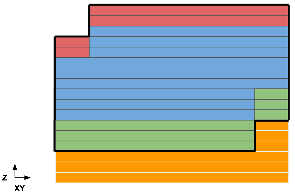
Surface Armor
Surface Armor 是一层部分烧结材料,添加在部件周围。这可以改善物理性能,降低翘曲风险,并通常可以提高部件质量。Surface Armor 难以去除,因此较厚的外壳可能会使部件取出和材料清理更加困难。
周长计数
如果周长计数最初设置为 0,则该设置使用的扫描算法不包括周长。添加周边可能完全无效,也可能导致意外行为。无周边的材料设置大多是旧的传统设置,在开发带有周边的设置时,请使用较新的设置作为起点。